
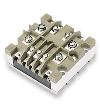
The MI-IAM is an accessory product to Vicor’s MI-200 and MI-J00 DC-DC converters that provides EMI filtering and transient protection. Designed for use with all 28 and 270 volt input converters, the MI-IAM can drive any number of modules with output loads up to 200 watts.
The MI-IAM meets the conducted emissions specifications of MIL-STD-461C/D/E and offers complete input transient, surge and spike protection to the most severe levels of MIL-STD-704A-F, MIL-STD-1275A/B/D and DO-160E. Reverse polarity protection and overvoltage lockout provide additional safeguards against potentially damaging line conditions. High power arrays can be configured using the expansion port capability of the MI-IAM.
- 28 Vdc (16 – 50 Vdc)
- 270 Vdc (125 – 400 Vdc)
- Up to 200 Watts from any combination of Vicor MI-200 or MI-J00 DC-DC converter modules
- 97%
- 2.28″ x 2.4″ x 0.5″(57,9 x 61,0 x 12,7 mm)
- -55°C to 100°C M-Grade
- MIL-STD-461C/D/E EMI compliance
- MIL-STD-704A-F, MIL-STD-1275A/B/D and DO-160E compliance for spikes and transients
- MIL-STD-810 environments compliance
- Short circuit protected
- Expansion port for additional power
Download Individual Chapters
- Zero-Current Switching
- DC-DC Converter Pinouts
- Module Dos and Donts
- Overcurrent Protection
- Output Voltage Trimming
- Multiple Gate In Connections
- Applications Circuits / Converter Array Design Considerations
- Using Boosters and Parallel Arrays
- EMC Considerations
- Optional Output Filters
- Battery Charger (BatMod)
Filter and Front-End Module Chapters
- AC Input Module (AIM / MI-AIM)
- Harmonic Attenuator Module (HAM)
- Input Attenuator Module (IAM / MI-IAM)
- Ripple Attenuator Module (RAM / MI-RAM)
- Offline Front End
Power System Chapters
- DC Input Power System (ComPAC / MI-ComPAC Family)
- AC Input Power System (FlatPAC Family)
- AC Input Power System (PFC FlatPAC)
General Chapters
Thermal Calculators
- Thermal data and heat sink selection tool
This is a downloadable Excel file.

| Description | P/N | Voltage Rating | Current Rating | RoHS | Technical Drawing | ||
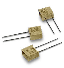 |
PC Tron | 30276 | 125 V | 5 A |

| Heat sinks used with Vicor’s VI-J00-size module (not Mini modules) | ||||||||
| Description | P/N | RoHS | Technical Drawing | |||||
 |
0.90″ Longitudinal Fins | 30191 | PDF | DXF | |||||
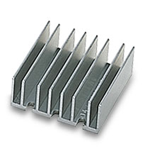 |
0.90″ Transverse Fins | 30771 | PDF | DXF | |||||
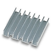 |
0.40″ Transverse Fins | 30140 | PDF | DXF | |||||
| Heat Sink Thermal Data and Calculator | ||||||||
| ThermMate Thermal Pads (10 pieces per package) | ||||||||
| Description | Thickness | P/N | RoHS | Technical Drawing | ||||
 |
For use with Vicor VI-J00 moduels only (not Mini modules) |
0.007″ | 20267 | PDF | DXF | ||||
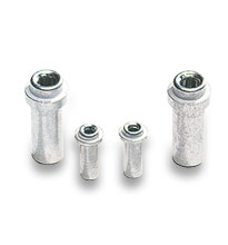
| Grounding Clips | ||||||||
| Description | P/N | RoHS | Technical Drawing | |||||
 |
For use with FinMod, Longitudinal 0.25″ Fins (-F1) | 32185 | PDF | DXF | |||||
| For use with FinMod, Longitudinal 0.50″ Fins (-F2) | 32185 | PDF | DXF | ||||||
| For use with FinMod, Transverse 0.25″ Fins (-F3) | 32186 | PDF | DXF | ||||||
| For use with FinMod, Transverse 0.50″ Fins (-F4) | 32186 | PDF | DXF | ||||||
| For use with SlimMod Flangless package (-S) | 32187 | PDF | DXF | ||||||