 What is Remote Sense?
It is a function that is used to detect the output load voltage and compensate for the voltage drop between the power supply output and the output load due to the resistance of the wire connecting them, if there was really a voltage drop.
When is Remote Sense used?
In general, low output voltage power supply, large output load current, long wire length, small wire cross-sectional area or high accuracy voltage circuit usually leads to the use of Remote Sense function for the power supply. There are 2 cases for using Remote Sense function.
Case 1: Voltage Accuracy Requirement can’t be fulfilled by the output load.
There is a power supply having its output voltage being 5V. Provided that the wire resistance is 0.1Ω and the output load current is 1A, meaning that the voltage drop between the power supply output and the output load is 0.1V.
(a) Voltage Accuracy Requirement: 5%/ Remote Sense function is not required, since Vload = 5V – 0.1V = 4.9V > 5V × (1-0.05) = 4.75V.
(b) Voltage Accuracy Requirement: 1%/ Remote Sense function is required, since Vload = 5V – 0.1V = 4.9V < 5V × (1-0.01) = 4.95V.
Case 2: Low output voltage power supply or long output cable exists.
In general, low output voltage power supply requires larger output current. Moreover, if the output load is placed farther from the power supply, which means having long cable, the cable loss increases.
Connection:
When it comes to connection of Remote Sense, there are mainly two things to be aware of, when you use the Remote Sense function of the power supply. The first thing is connecting Remote Sense leads to the output load. The second thing is preventing noise by twisting. The following two sections state these two things in detail.
(a) Remote Sense leads Connection: Firstly, in general, there are 2 pins for Remote Sensing from the power supply, Sense+ and Sense-, or S+ and S-. These 2 pins should be connected by the Remote Sense leads to the positive and negative side of the output load respectively.
(b) Remote Sense leads twisting: Secondly, noise shall be prevented. This is done by twisting the Remote Sense leads, S+ and S-, together.
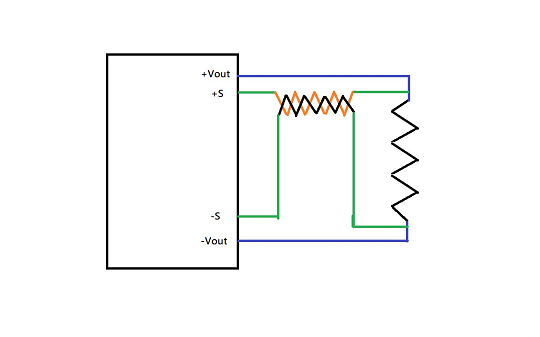 The Figure below shows proper Remote Sense connection.
Limit:
(a) Over Voltage Protection: The first limit is Over Voltage Protection, OVP. Briefly speaking, OVP means the protection of the power supply, when the output voltage exceeds the design limit of the power supply.
Since the use of remote sense function leads to the raise of the output voltage of the power supply, it might trigger the over voltage protection, leading to the shutdown of the output of the power supply.
Therefore, please check the OVP set point of the power supply.
(b) Compensation Range: The other limit is compensation range. Typically, it ranges from 0.3V to 1.0V. However, the exact maximum remote sense compensating range shall be checked on the datasheet of the corresponding power supply.
Application:
Remote Sensing can be applied to precision measurement systems, sensitive electronic devices, or equipment. The following two sections describe the reason why Remote Sensing shall apply to precision measurement systems, sensitive electronic devices, or equipment.
(a) Precision Measurement Systems: In this section, the objective is to prove the necessity of the existence of the Remote Sense in precision measurement systems.
According to the image below, the blue line indicates that the output voltage of the output load of CQB150W-24S12 without using Remote Sense in precision measurement systems drops more compared to that of the orange line, which is using Remote Sense. Since precision measurement systems requires the accurate output load voltage, the one using Remote Sense having constant voltage can be implemented instead of the one without using Remote Sense.
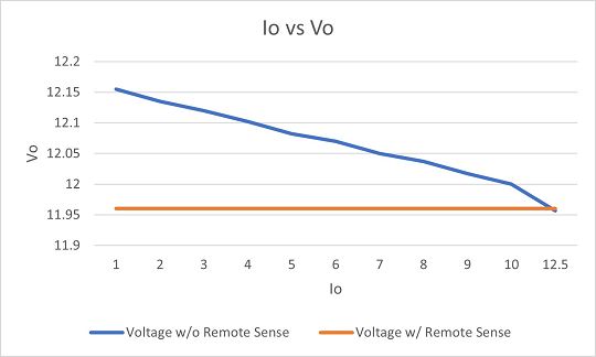
Thus, Remote Sense shall be implemented in precision measurement systems.
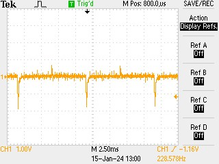
(b) Sensitive Electronic Devices (Equipment): In this section, the objective is to prove Remote Sense is beneficial to the sensitive electronic devices. In order to do so, the waveform of the output voltage of the output load of CQB150W-24S12 is shown below, when the output current is changed from 100%-0%-100%, in case of having and without the connection the Remote Sense pins.
The image on the left below is the voltage waveform of the output load with the Remote Sense function using in sensitive electronic devices or equipment. It has the stabler waveform compared to the one on the right, which is not using Remote Sense function.
Since sensitive electronic devices or equipment requires stabler output load voltage, the one using Remote Sense is acceptable, whilst the other one is not acceptable.
 |
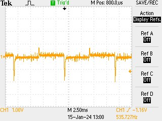 |
Four regions expanded by the arrow: 100%-0%-100%-0%
To sum up, the stabler voltage of the output load emphasizes that the Remote Sense shall be applied in the sensitive electronic devices or equipment.
Contact us if you need more support: office@vitecpower.com