
The VI-200 and VI-J00 Seriesof DC-DC converters have set the standard for high power, low noise, reliability and ease-of-use in the component power industry. Thousands of combinations of input voltages, output voltages and power levels means not having to compromise when selecting modules for your power system. These power modules are field proven with an installed base of over 15 million units.
Compact and efficient, VI-200 and VI-J00 converters feature wide input voltage ranges, remote sense, enhanced output programmability, and low standby dissipation. Power boosters provide a simple, cost-effective solution for higher power requirements up to kilowatts. VI-200 products also offer output overvoltage protection and thermal shutdown. VI-J00 units can operate to 100°C baseplate temperatures.
These units are available in several different temperature grades (down to -55°C operation and -65°C storage) and with different baseplate styles. The electronic circuitry is a fully encapsulated for protection in harsh environments and models are available with integral heat sinks.
Input Voltages:
- 10 – 400 Vdc
Output Voltages:
- 1 – 95 Vdc
Output Power: (per module)
- VI-200: 50 – 200 W
- VI-J00: 25 – 100 W
Dimensions:
- VI-200 (full brick): 4.6″ x 2.4″ x 0.5″(116,9 x 61,0 x 12,7 mm)
- VI-J00 (half brick): 2.28″ x 2.4″ x 0.5″(57,9 x 61,0 x 12,7 mm)
- Up to 50 W/In3
- Remote sense and current limit
- Overvoltage protection, thermal shutdown (VI-200 / VE-200)
- Logic enable/disable
- Wide range output adjust
- Compatible power booster modules (VI-200 / VE-200)
- ZCS power architecture
- Low noise FM control
- Soldering Methods and Procedures for Vicor Power Modules
- Powering Dynamic Loads
- Designing a Power Supply with Multiple Input Options
- Creating High Voltage Outputs
- Using Modular DC-DC Converters to Meet European Standards for Railway Applications
- Current Share Board
- Constant Current Control for DC-DC Converters
- Undervoltage / Overvoltage Lockout
Download Entire Manual
Download Individual Chapters
- Zero-Current Switching
- DC-DC Converter Pinouts
- Module Dos and Donts
- Overcurrent Protection
- Output Voltage Trimming
- Multiple Gate In Connections
- Applications Circuits / Converter Array Design Considerations
- Using Boosters and Parallel Arrays
- EMC Considerations
- Optional Output Filters
- Battery Charger (BatMod)
Filter and Front-End Module Chapters
- AC Input Module (AIM / MI-AIM)
- Harmonic Attenuator Module (HAM)
- Input Attenuator Module (IAM / MI-IAM)
- Ripple Attenuator Module (RAM / MI-RAM)
- Offline Front End
Power System Chapters
- DC Input Power System (ComPAC / MI-ComPAC Family)
- AC Input Power System (FlatPAC Family)
- AC Input Power System (PFC FlatPAC)
General Chapters
VI-200 / VE-200 Family DC-DC Converters
- cURus – UL 60950-1, CSA 60950-1
- cTÜVus – EN 60950-1, UL 60950-1, CSA 60950-1
- CE Marked – Low Voltage Directive (2006/95/EC)
- CE Marked – Low Voltage Directive (2006/95/EC) and RoHS Recast Directive (2011/65/EU)
- CB Certificate – IEC 60950-1:2001
- Module Safety Instruction Sheet
VI-J00 / VE-J00 Family DC-DC Converters
- cURus – UL 60950-1, CSA 60950-1
- cTÜVus – EN 60950-1, UL 60950-1, CSA 60950-1
- CE Marked – Low Voltage Directive (2006/95/EC)
- CE Marked – Low Voltage Directive (2006/95/EC) and RoHS Recast Directive (2011/65/EU)
- CB Certificate – IEC 60950-1:2001
- Module Safety Instruction Sheet
| VI-/VE-200 and VI-/VE-J00 Modules | ||||
| 2-D Full-Size VI-200 / VE-200 DC-DC Converter Module Drawings | ||||
| Drwg. Number | Description | Download | RoHS | |
| 05429 | Outline drawing for full-size VI-200 / VE-200 DC-DC converter | DXF | PDF | ||
| 3-D Full-Size VI-200 / VE-200 Module (referring to drawing number 05429) | ||||
| Non-RoHS, VI-2xx series | STEP | 3D PDF | |||
| RoHS, VI-2xx series | STEP | 3D PDF | |||
| 2-D Half-Size VI-J00 / VE-J00 DC-DC Converter Module Drawings | ||||
| Drwg. Number | Description | Download | RoHS | |
| 03550 | Outline drawing for half-size VI-J00 / VE-J00 DC-DC converter | DXF | PDF | ||
| 3-D Half-Size VI-J00 / VE-J00 Module (referring to drawing number 03550) | ||||
| Non-RoHS, VI-Jxx series | STEP | 3D PDF | |||
| RoHS, VI-Jxx series | STEP | 3D PDF | |||
| FinMod Modules (Flangeless package with integral heat sink) | ||||
| 2-D Full-Size FinMod-size Drawings (-F1) | ||||
| Drwg. Number | Description | Download | RoHS | |
| 06181 | Outline drawing for full-size FinMod DC-DC converter (-F1) | DXF | PDF | ||
| 3-D Full-Size FinMod Module (referring to drawing number 06181) | ||||
| Non-RoHS, VI-200 Driver and Booster series with 0.25″ longitudinal heat sink (VI-2xx-xx-F1 / VI-Bxx-xx-F1) |
STEP | 3D PDF | |||
| RoHS, VE-200 Driver and Booster series with 0.25″ longitudinal heat sink (VE-2xx-xx-F1 / VE-Bxx-xx-F1) |
STEP | 3D PDF | |||
| 2-D Full-Size FinMod-size Drawings (-F2) | ||||
| Drwg. Number | Description | Download | RoHS | |
| 06185 | Outline drawing for full-size FinMod DC-DC converter (-F2) | DXF | PDF | ||
| 3-D Full-Size FinMod Module (referring to drawing number 06185) | ||||
| Non-RoHS, VI-200 Driver and Booster series with 0.25″ transverse heat sink (VI-2xx-xx-F2 / VI-Bxx-xx-F2) |
STEP | 3D PDF | |||
| RoHS, VE-200 series with 0.25″ transverse heat sink (VE-2xx-xx-F2) | STEP | 3D PDF | |||
| 2-D Full-Size FinMod-size Drawings (-F3) | ||||
| Drwg. Number | Description | Download | RoHS | |
| 06159 | Outline drawing for full-size FinMod DC-DC converter (-F3) | DXF | PDF | ||
| 3-D Full-Size FinMod Module (referring to drawing number 06159) | ||||
| Non-RoHS, VI-200 Driver and Booster series with 0.5″ longitudinal heat sink (VI-2xx-xx-F3 / VI-Bxx-xx-F3) |
STEP | 3D PDF | |||
| RoHS, VE-200 series with 0.5″ longitudinal heat sink (VE-2xx-xx-F3) | STEP | 3D PDF | |||
| 2-D Full-Size FinMod-size Drawings (-F4) | ||||
| Drwg. Number | Description | Download | RoHS | |
| 06161 | Outline drawing for full-size FinMod DC-DC converter (-F4) | DXF | PDF | ||
| 3-D Full-Size FinMod Module (referring to drawing number 06161) | ||||
| Non-RoHS, VI-200 Driver and Booster series with 0.5″ transverse heat sink (VI-2xx-xx-F4 / VI-Bxx-xx-F4) |
STEP | 3D PDF | |||
| RoHS, VE-200 series with 0.5″ transverse heat sink (VE-2xx-xx-F4) | STEP | 3D PDF | |||
| 2-D Half-Size FinMod-size Drawings (-F1) | ||||
| Drwg. Number | Description | Download | RoHS | |
| 06183 | Outline drawing for half-size FinMod DC-DC converter (-F1) | DXF | PDF | ||
| 3-D Half-Size FinMod Module (referring to drawing number 06183) | ||||
| Non-RoHS, VI-J00 series with 0.25″ longitudinal heat sink (VI-Jxx-xx-F1) | STEP | 3D PDF | |||
| RoHS, VE-J00 series with 0.25″ longitudinal heat sink (VE-Jxx-xx-F1) | STEP | 3D PDF | |||
| 2-D Half-Size FinMod-size Drawings (-F2) | ||||
| Drwg. Number | Description | Download | RoHS | |
| 06187 | Outline drawing for half-size FinMod DC-DC converter (-F2) | DXF | PDF | ||
| 3-D Half-Size FinMod Module (referring to drawing number 06187) | ||||
| Non-RoHS, VI-J00 series with 0.5″ longitudinal heat sink (VI-Jxx-xx-F2) | STEP | 3D PDF | |||
| RoHS, VE-J00 series with 0.5″ longitudinal heat sink (VE-Jxx-xx-F2) | STEP | 3D PDF | |||
| 2-D Half-Size FinMod-size Drawings (-F3) | ||||
| Drwg. Number | Description | Download | RoHS | |
| 05997 | Outline drawing for half-size FinMod DC-DC converter (-F3) | DXF | PDF | ||
| 3-D Half-Size FinMod Module (referring to drawing number 05997) | ||||
| Non-RoHS, VI-J00 series with 0.25″ transverse heat sink (VI-Jxx-xx-F3) | STEP | 3D PDF | |||
| RoHS, VE-J00 series with 0.25″ transverse heat sink (VE-Jxx-xx-F3) | STEP | 3D PDF | |||
| 2-D Half-Size FinMod-size Drawings (-F4) | ||||
| Drwg. Number | Description | Download | RoHS | |
| 06157 | Outline drawing for half-size FinMod DC-DC converter (-F4) | DXF | PDF | ||
| 3-D Half-Size FinMod Module (referring to drawing number 06157) | ||||
| Non-RoHS, VI-J00 series with 0.5″ transverse heat sink (VI-Jxx-xx-F4) | STEP | 3D PDF | |||
| RoHS, VE-J00 series with 0.5″ transverse heat sink (VE-Jxx-xx-F4) | STEP | 3D PDF | |||
| SlimMod Modules (Flangeless package) | ||||
| 2-D Full-Size SlimMod Module Drawings | ||||
| Drwg. Number | Description | Download | RoHS | |
| 04713 | Outline drawing for full-size SlimMod DC-DC converter | DXF | PDF | ||
| 3-D Full-Size SlimMod Module (referring to drawing number 04713) | ||||
| Non-RoHS, VI-200 series SlimMod (VI-2xx-xx-S) | STEP | 3D PDF | |||
| RoHS, VEI-200 series SlimMod (VE-2xx-xx-S) | STEP | 3D PDF | |||
| 2-D Half-Size SlimMod Module Drawings | ||||
| Drwg. Number | Description | Download | RoHS | |
| 04712 | Outline drawing for half-size SlimMod DC-DC converter | DXF | PDF | ||
| 3-D Half-Size SlimMod Module (referring to drawing number 04712) | ||||
| Non-RoHS, VI-J00 series SlimMod (VI-Jxx-xx-S) | STEP | 3D PDF | |||
| RoHS, VE-J00 series SlimMod (VE-Jxx-xx-S) | STEP | 3D PDF | |||
These calculator programs allow users to determine values that help with accessory component selection for power system design. Trim Resistor Calculators
- Trim resistors for fixed output voltage trimming
- Trim resistors for variable output voltage trimming
Thermal Calculators
- Thermal impedance calculator
- Thermal data and heat sink selection tool
This is a downloadable Excel file.
- FIAM – Filter Input Attenuator Module – DC input, front-end modules provides EMI filtering, transient protection, and inrush current limiting in DC-DC applications.
- IAM – Input Attenuator Module – DC input, front-end module providing transient protection, inrush current limiting and EMI filtering for VI-200 and VI-J00 DC-DC converters.
- QPI Family Input Filters – QPIs provide common-mode and differential-mode attenuation from 150 kHz to 30 MHz in a 1.0″ x 1.0″ (25 x 25 mm) surface mount package.
- RAM – Ripple Attenuator Module – The RAM may be connected to VI-200 or VI-J00 converters with output voltages from 5 – 50 Volts, to limit total output noise to less than 3 mV peak-to-peak at loads up to 20 Amps.
- MicroRAM – Output Ripple Attenuator Module – The MicroRAM combines both active and passive filtering to achieve greater than 40 dB of noise attenuation from over a range of 3 – 30 Vdc.
- QPO Family Output Filters – QPO filters use active filtering to reduce power supply ripple and noise in a 1.0″ x 1.0″ (25 x 25 mm) surface mount package.
- AIM – AC Input Front-end Module – The AIM is an AC front-end module which interfaces directly with worldwide AC mains to provide line rectification, EMI filtering, transient protection, and inrush limiting.
- ARM – Autoranging Rectifier Module – The ARM is the front end of a switching power supply and uses a microprocessor to control strapping of the voltage doubler.
- FARM – Filter / Autoranging Rectifier Module – The FARM is an AC front-end module which provides EMI filtering, autoranging line rectification and inrush current limiting.
- ENMods – Modular AC Front-end System – The ENMods system combines EMI filtering with the FARM and MiniHAM modules creating an AC front end fully compliant with European norms for harmonic current limits, EMI and input transient immunity.
- Off-line Front End – Vicors family of off-line front ends interface any 300 Vin DC-DC converters or configurable products, to 100, 115, 230 or 240 Vac single-phase and 208 Vac three-phase mains.
- High-Boost HAM – AC Harmonic Attenuator Module – The HAM module is a full-wave rectifier with a high-frequency zero-current switching (ZCS) boost converter providing up to 675 Watts of power in a full-brick package.
| Description | P/N | RoHS | Technical Drawing | |||||
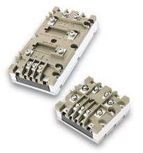 |
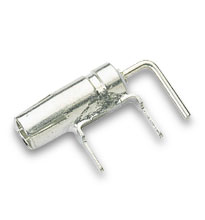
Rugged chassis-mount housing for VI-200 module* (add-B1 suffix to module number for preinstalled) | 06322 | PDF | DXF | |||||
| Rugged chassis-mount housing for VI-J00 module* (add-B1 suffix to module number for preinstalled) | 18952 | PDF | DXF | ||||||
| RoHS, VI-J00 series BusMod (VI-J-xx-xx-B1) | 18952 | STEP | ISG | ||||||
| *Not for use with HAM module. | ||||||||
| Description | P/N | Capacitance | Voltage Rating | RoHS | Technical Drawing | ||||||
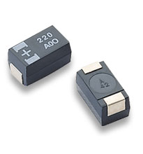 |
SMT Polymer | 23484-337 | 330 µF | 6.3 V | PDF | DXF | ||||||
| SMT Polymer | 23484-477 | 470 µF | 6.3 V | PDF | DXF | |||||||
| SMT Polymer | 23579-227 | 220 µF | 10 V | PDF | DXF | |||||||
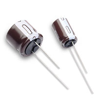 |
Al-El (10 mm x 16 mm) | 30468 | 270 µF | 25 V | |||||||
| Al-El (16 mm x 15 mm) | 33985 | 820 µF | 25 V | ||||||||
| Al-El (10 mm x 16 mm) | 30788 | 68 µF | 63 V | ||||||||
| Al-El (10 mm x 16 mm) | 30787 | 220 µF | 63 V | ||||||||
| Al-El (10 mm x 50 mm) | 34837-108 | 10 µF | 63 V | ||||||||
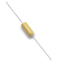 |
Tantalum | 30800 | 270 µF | 10 V | |||||||
| Tantalum | 30506 | 120 µF | 20 V | ||||||||
| Tantalum | 30507 | 68 µF | 30 V | ||||||||
| Tantalum | 30259 | 27 µF | 50 V | ||||||||
|
X-Capacitor | 04068 | 0.22 µF | 250 Vac | |||||||
| X Capacitor | 03047 | 0.47 µF | 250 Vac | ||||||||
| X Capacitor | 02573 | 1 µF | 250 V | ||||||||
| X Capacitor | 03269 | 0.15 µF | 310 V | ||||||||
| X Capacitor | 00927 | 0.33 µF | 275 V | ||||||||
 |
Y-Cap Surface Mount | 25283 | 4,700 pF | 250 Vac | |||||||
| Y-Cap | 03285 | 4,700 pF | 250 Vac | ||||||||
| Y-Cap | 30802 | 1,500 pF | 250 V | ||||||||
| Y-Cap | 00770 | 1,500 pF | 250 Vac | PDF | DXF | |||||||
| Y-Cap | 01000 | 4,700 pF | 250 Vac | ||||||||
| Y-Cap | 33643 | 0.01 µF | 250 V | ||||||||
| Y-Cap | 03093 | 0.022 µF | 250 V | ||||||||
| Multilayer Film Cap | 34610 | 0.61 µF | 250 V | PDF | DXF | |||||||
| Ceramic Capacitors | 28054 | 0.01 µF | 500 V | ||||||||
| Ceramic Capacitors | 30458 | 470 pF | 500 V | ||||||||
| Holdup Capacitors | 30240 | 270 µF | 400 Vac | ||||||||
| Holdup Capacitors | 30249 | 470 µF | 450 Vac | ||||||||
| Holdup Capacitors | 30769 | 270 µF | 200 Vac | ||||||||

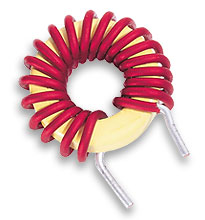
| Common Mode | ||||||||||||
| Description | P/N | Inductance | Rated Current | DCR (max) |
RoHS | Technical Drawing | ||||||
 |
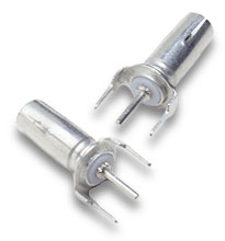
Common-mode input | 37052-601 | 600 µH | 10 A | – | |||||||
| Common-mode input | 31743 | 1,000 µH | 12 A | 6.5 mΩ | PDF | DXF | |||||||
| Common-mode input | 32006 | 1,300 µH | 13 A | 14 mΩ | PDF | DXF | |||||||
| Common-mode input | 31943 | 2,163 µH | 1 A | 42 mΩ | PDF | DXF | |||||||
| Common-mode input | 31742 | 3,000 µH | 7 A | 18 mΩ | PDF | DXF | |||||||
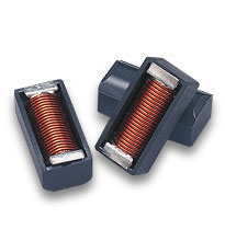
 |
Common-mode output | 36-00029-06 | 70 µH | 80 A | 0.4 mΩ | |||||||
| Common-mode output | 36-00029-07 | 110 µH | 60 A | 0.6 mΩ | ||||||||
| Common-mode output | 36-00029-01 | 335 µH | 40 A | 2 mΩ | PDF | DXF | |||||||
| Common-mode output | 36-00037 | 420 µH | 20 A | 5 mΩ | ||||||||
| Common-mode output | 36-00029-04 | 1,270 µH | 10 A | 10 mΩ | PDF | DXF | |||||||
| Differential Mode | ||||||||||||
 |
Differential-mode input | 33206 | 22 µH | 12 A | 5.5 mΩ | PDF | DXF | ||||||
| Differential-mode input | 36-00036 | 1,000 µH | 4 A | 250 mΩ | – | |||||||
|
|
||||||||||||
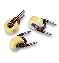 |
Differential-mode output | 30268 | 0.2 µH | 40 A | – | PDF | DXF | ||||||
| Differential-mode output | 32012 | 27 µH | 12 A | – | ||||||||
| Differential-mode output | 32497 | 1.8 µH | 10 A | – | PDF | DXF | |||||||
| Output-sense compensation | 36-00030 | 1,000 µH | – | – | ||||||||
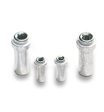
| Surface Mount | Download Surface-Mount Inductor Data Sheet | |||||||||||
 |
Surface-mount inductor | 31499-16 | 0.37 µH | 100 A | 0.23 mΩ | PDF | DXF | ||||||
| Surface-mount inductor | 31499-15 | 0.66 µH | 75 A | 0.42 mΩ | PDF | DXF | |||||||
| Surface-mount inductor | 31499-14 | 1.03 µH | 60 A | 0.58 mΩ | PDF | DXF | |||||||
| Surface-mount inductor | 31499-13 | 1.48 µH | 50 A | 0.82 mΩ | PDF | DXF | |||||||
| Surface-mount inductor | 31499-12 | 2.62 µH | 37.5 A | 1.43 mΩ | PDF | DXF | |||||||
| Surface-mount inductor | 31499-10 | 5.90 µH | 25 A | 3.23 mΩ | PDF | DXF | |||||||
| Surface-mount inductor | 31499-08 | 13.2 µH | 16.6 A | 7.56 mΩ | PDF | DXF | |||||||
| Surface-mount inductor | 31499-05 | 47.4 µH | 8.8 A | 29.4 mΩ | PDF | DXF | |||||||
| Surface-mount inductor | 31499-03 | 133 µH | 5.6 A | 81.2 mΩ | PDF | DXF | |||||||
| Surface-mount inductor | 31499-02 | 243 µH | 3.9 A | 156 mΩ | PDF | DXF | |||||||

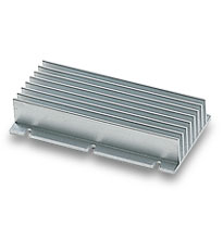
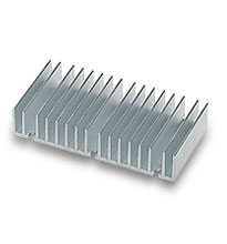
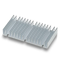
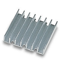
| Heat sinks used with Vicors VI-200 module (not for Maxi modules) | |||||||||||
| Description | P/N | RoHS | Technical Drawing | ||||||||
 |
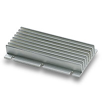
0.90″ Longitudinal Fins | 30089 | PDF | DXF | ||||||||
 |
0.90″ Transverse Fins | 30090 | PDF | DXF | ||||||||
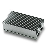
 |
0.70″ Longitudinal Fins | 30775 | PDF | DXF | ||||||||
 |
0.70″ Transverse Fins | 30193 | PDF | DXF | ||||||||
 |
1.45″ Longitudinal Fins | 30780 | PDF | DXF | ||||||||
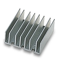
 |
0.40″ Transverse Fins | 30194 | PDF | DXF | ||||||||
| Heat Sink Thermal Data and Calculator | |||||||||||
| Heat sinks used with Vicors VI-J00 module (not Mini modules) | |||||||||||
| Description | P/N | RoHS | Technical Drawing | ||||||||
 |
0.90″ Longitudinal Fins | 30191 | PDF | DXF | ||||||||
 |
0.90″ Transverse Fins | 30771 | PDF | DXF | ||||||||
 |
0.40″ Transverse Fins | 30140 | PDF | DXF | ||||||||
| Heat Sink Thermal Data and Calculator |
|||||||||||
| ThermMate Thermal Pads (10 pieces per package) | |||||||||||
| Description | P/N | Thickness | RoHS | Technical Drawing | |||||||
 |
For use with Vicor VII-200 modules* | 20266 | 0.007″ | PDF | DXF | |||||||
| For use with Vicor VI-J00 modules* | 20267 | 0.007″ | PDF | DXF | ||||||||
| * NOT for use with Vicor Maxi or Mini modules | |||||||||||
| Grounding Clips | |||||||||||
| Description | P/N | RoHS | Technical Drawing | ||||||||
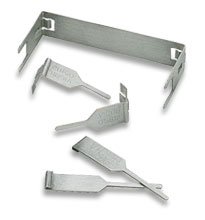 |
For use with FinMod, Longitudinal 0.25″ Fins (-F1) | 32185 | PDF | DXF | ||||||||
| For use with FinMod, Longitudinal 0.50″ Fins (-F2) | 32185 | PDF | DXF | |||||||||
| For use with FinMod, Transverse 0.25″ Fins (-F3) | 32186 | PDF | DXF | |||||||||
| For use with FinMod, Transverse 0.50″ Fins (-F4) | 32186 | PDF | DXF | |||||||||
| For use with SlimMod Flangless package (-S) | 32187 | PDF | DXF | |||||||||