
The VIPAC family of power systems is a new class of user- defined, modular power solutions for Military COTS applications. It incorporates either Vicor’s M-FIAM5B or M-FIAM9 , which provides EMI filtering and transient protection, Vicor Maxi, Mini and Micro series DC-DC converters (H- or M-Grade), and a choice of output connections and mechanical platforms. The MIL-COTS VIPAC can be specified with one, two or three outputs with voltages as low as 3.3 Vdc to as high as 48 Vdc and power levels from 50 – 400 Watts per output. The VIPAC is available with a 28 Vdc input in a variety of packages with profiles as low as 0.75″.
- 28 Vdc
- 3.3 – 48 Vdc
- 50 – 400 W
- -55 to 65°C (ambient M-Grade)
- See mechanical drawing on data sheet
- Single, dual or triple outputs
- MIL-STD-461E EMI compliance
- Input transient protection
– MIL-STD-704E/F (M-FIAM5B)
– MIL-STD-704A/E/F and MIL-STD-1275A/B/D (M-FIAM9) - Compliant to MIL-STD-810F for shock and vibration
- Vibration: Method 514.5, Procedure I (20-2000 Hz at 5 grms)
- Shock: Method 516.5, Procedure I (40 g for 15 – 23 ms and 75 g for 8-13 ms)
- Environmental stress screening (modules only)
- Two output termination styles
- Low profile
24 Vdc (18 – 36 V) Input Maxi, Mini, Micro Data Sheets
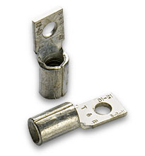
| DC Input using both PlugMate and LugMate | |||||||||||
| Drawing Number |
Description | Maxi | Mini | Micro | RoHS | Technical Drawing | |||||
| 21317 | VIPAC Power System Configuration “A” | 3 | PDF | DXF | ||||||||
|
|
|||||||||||
| 21318 | VIPAC Power System Configuration “B” | 2 | PDF | DXF | ||||||||
| 21319 | VIPAC Power System Configuration “C” | 2 | PDF | DXF | ||||||||
| 21320 | VIPAC Power System Configuration “D” | 2 | PDF | DXF | ||||||||
| 21321 | VIPAC Power System Configuration “E” | 1 | PDF | DXF | ||||||||
| 21322 | VIPAC Power System Configuration “F” | 1 | PDF | DXF | ||||||||
| 21231 | VIPAC Power System Configuration “G” | 1 | PDF | DXF | ||||||||
These calculator programs allow users to determine values that help with accessory
component selection for power system design.
Trim Resistor Calculators
| For 28 V MIL-COTS VIPAC | ||||||||
| Description | P/N | Technical Drawing | ||||||
 |
DC Input Connector | 21394 | – | |||||
| Input/Output Interface Connector | 22988 | |||||||
| VIPAC Mating Connector Kit | 23487R | – | ||||||

| Description | P/N | Technical Drawing | ||||||
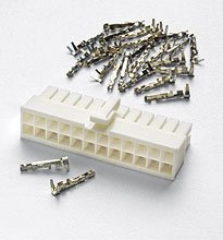 |
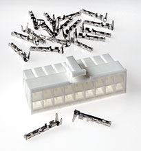
Maxi PlugMate Housing (for 24 Pins) | 25044 | – | |||||
| Maxi PlugMate Pins (24) | 24796 | – | ||||||
| Maxi PlugMate Connector Kit | 25061* | – | ||||||
| * Includes Housing and (24) Pins | ||||||||
 |
Mini PlugMate Housing (for 18 Pins) | 25050 | – | |||||
| Mini PlugMate Pins (18) | 24796 | – | ||||||
| Mini PlugMate Connector Kit | 25067* | – | ||||||
| * Includes Housing and (18) Pins | ||||||||
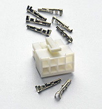 |
Micro PlugMate Housing (for 8 Pins) | 25056 | – | |||||
| Micro PlugMate Pins (8) | 24796 | – | ||||||
| Micro PlugMate Connector Kit | 25073* | – | ||||||
| * Includes Housing and (8) Pins | ||||||||
| Description | P/N | Technical Drawing | ||||||
 |
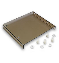
Long Standoff Kit | 23709R | – | |||||
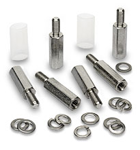 |
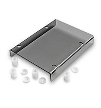
Short Standoff Kit | 23710R | – | |||||