

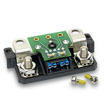
The M-FIAM is a DC front-end module that provides EMI filtering and transient protection. The M-FIAM line of products enables designers using Vicor’s 24, 28 or 300 Vin Maxi, Mini, Micro DC-DC converters or 28 Vin MIL-COTS V•I Chip modules to meet conducted emission / conducted susceptibility per MIL-STD-461E and input transient surges per MIL-STD-704 or MIL-STD-1275. In addition, the MVA-FIAM5B and MVA-FIAM9 offers designers using the M-FIAM5B or M-FIAM9 the capability of coldplate mounting with convenient input and output connectors.
- M-FIAM3: 180 – 375 Vdc
- M-FIAM5B / MVA-FIAM5B: 14 – 36 Vdc
- M-FIAM7 / M-FIAM7B: 14 – 50 Vdc
- M-FIAM9 / MVA-FIAM9: 10 – 36 Vdc
- M-FIAM3: 3 Amps
- M-FIAM5B / MVA-FIAM5B: 20 Amps
- M-FIAM7: 10 Amps
- M-FIAM7B: 25 Amps
- M-FIAM9 / MVA-FIAM9: 18 Amps
- M-FIAM3: MIL-STD-740E/F
- M-FIAM5B / MVA-FIAM5B: MIL-STD-704E/F
- M-FIAM7: MIL-STD-704A-F, MIL-STD1275A/B/D, DO-160E
- M-FIAM9 / MVA-FIAM9: MIL-STD-704A-F, MIL-STD1275A/B/D
- M-FIAM3: 300 Vin Maxi, Mini, Micro
- M-FIAM5B / MVA-FIAM5B: 24/28 Vin Maxi, Mini, Micro
- M-FIAM7 / M-FIAM7B: 28 Vin MIL-COTS VI•Chips
- M-FIAM9 / MVA-FIAM9: 24/28 Vin Maxi, Mini, Micro
- M-FIAM: 2.28″ x 2.2″ x 0.5″
(57,9 x 55,9 x 12,7 mm) - MVA-FIAM: 4.69″ x 3.62″ x 0.81″
(119,4 x 92,0 x 20,6 mm)
- MIL-STD-461F EMI compliance
- Inrush current limiting
- Low profile mounting option
Download Individual Chapters
- High Density DC-DC Converter Technology
- Control Pin Functions and Applications
- Design Requirements
- EMC Considerations
- Current Sharing in Power Arrays
- Thermal Performance Information
Accessory Modules
- Autoranging Rectifier Module (ARM)
- Filter / Autoranging Rectifier Module (FARM)
- Modular AC Front-end System (ENMod)
- High Boost HAM
- Filter Input Attenuator Module (FIAM)
- Output Ripple Attenuator Module (MicroRAM)
Recommended Soldering Methods
Mounting Options
This calculator program allow users to determine values that help with accessory component selection for power system design.
Thermal Calculators
- Thermal data and heat sink selection tool
This is a downloadable Excel file.


| Description | P/N | Voltage Rating | Current Rating | RoHS | Technical Drawing | ||
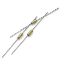 |
Fuse | 30247 | 125 V | 10 A |
 |
SurfMates – Surface-mount Sockets | ||||||||||||
| Board Thickness | Mounting | Assembly Drawing | Converter Pin Style* | Module Style | Input P/N** |
Output P/N** | 5 In/Out Sets P/N | Technical Drawing | |||||
| All | surface | PDF | DXF | F | Mini | 22100 | 22102 | 16021 | PDF | DXF | |||||
| Example of SurfMate Application | |||||||||||||
| * F = Short Gold (RoHS), G = Long Gold (RoHS) ** For individual input / output purchases, a 35-piece minimum (and multiples) applies to Maxis / Minis and a 40-piece minimum (and multiples) for Micros. |
|||||||||||||
 |
InMates – Through-hole | ||||||||||||
| All sockets are supplied on InMate headers to assure proper alignment during installation. | |||||||||||||
| Board Thickness (nominal) | Board Thickness (min / max) |
Mounting | Converter Pin Style* | Module Style | Input P/N** | Output P/N** | 5 In/Out Sets P/N | Technical Drawing | |||||
| 0.063″ | 0.055″ / 0.071″ | inboard | F | Mini | 18374 | 18384 | 18366 | PDF | DXF | |||||
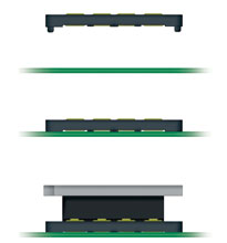
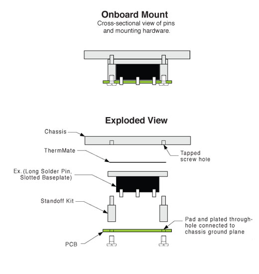
| 0.063″ | 0.055″ / 0.071″ | onboard | G | Mini | 18378 | 18390 | 18368 | PDF | DXF | |||||
| 0.094″ | 0.084″ / 0.104″ | inboard | F | Mini | 18375 | 18385 | 18367 | ||||||
| 0.094″ | 0.084″ / 0.104″ | onboard | G | Mini | 18379 | 18391 | 18369 | ||||||
| 0.125″ | 0.1125″ / 0.1375″ | onboard | G | Mini | 21539 | 21544 | 21511 | ||||||
| Example of Inboard Mounting Options Example of Onboard Mounting Options | |||||||||||||
| * F = Short Gold (RoHS), G = Long Gold (RoHS) ** For individual input / output purchases, a 35-piece minimum (and multiples) applies to Maxis / Minis and a 40-piece minimum (and multiples) for Micros. |
|||||||||||||
| Module Exchange Tools | |||||||||||||
| Description | Module Style | P/N | Technical Drawing | ||||||||||
 |
Used to facilitate the proper extraction of Mini modules from InMate or SurfMate sockets. | Mini | 22828 | – | |||||||||
 |
Standoff Kits for Solder Mounted Modules | |||||||||||||||
| Board Thickness | Mounting | Converter Pin Style | Baseplate | Heat Sink | Kit P/N* | Bag P/N** | Technical Drawing | |||||||||
| 0.063″ | inboard | F, Blank | slotted | thru-hole | 18150 | 19126 | PDF | DXF | |||||||||
| 0.063″ | inboard | F, Blank | slotted | threaded | 18151 | 19127 | PDF | DXF | |||||||||
| 0.063″ | inboard | F, Blank | thru-hole | thru-hole | 18146 | 19122 | PDF | DXF | |||||||||
| 0.063″ | inboard | F, Blank | thru-hole | threaded | 18147 | 19123 | PDF | DXF | |||||||||
| 0.063″ | inboard | F, Blank | threaded | thru-hole | 18146 | 19122 | PDF | DXF | |||||||||
| 0.063″ | onboard | G, L | slotted | thru-hole | 18156 | 19132 | PDF | DXF | |||||||||
| 0.063″ | onboard | G, L | slotted | threaded | 18157 | 19133 | PDF | DXF | |||||||||
| 0.063″ | onboard | G, L | thru-hole | thru-hole | 18150 | 19126 | PDF | DXF | |||||||||
| 0.063″ | onboard | G, L | thru-hole | threaded | 18152 | 19128 | PDF | DXF | |||||||||
| 0.063″ | onboard | G, L | threaded | thru-hole | 18150 | 19126 | PDF | DXF | |||||||||
| 0.093″ | inboard | G, L | slotted | thru-hole | 18150 | 19126 | PDF | DXF | |||||||||
| 0.093 “ | inboard | G, L | slotted | threaded | 18151 | 19127 | PDF | DXF | |||||||||
| 0.093 “ | inboard | G, L | thru-hole | thru-hole | 18146 | 19122 | PDF | DXF | |||||||||
| 0.093 “ | inboard | G, L | thru-hole | threaded | 18147 | 19123 | PDF | DXF | |||||||||
| 0.093 “ | inboard | G, L | threaded | thru-hole | 18146 | 19122 | PDF | DXF | |||||||||
| * Kits include six (6) standoffs and screws. Mini and Micro modules require a minimum of four standoffs. ** Bags of one hundred (100) do not include screws; #4-40 thread hardware required. |
||||||||||||||||
| Design Information for Solder Mounting | ||||||||||||||||
| |
Standoff Kits for InMate Mounted Modules | |||||||||||||||
| Board Thickness | Mounting | Converter Pin Style | Baseplate | Heat Sink | Kit P/N* | Bag P/N** | Technical Drawing | |||||||||
| 0.063″ | inboard | S | slotted | thru-hole | 18153 | 19129 | PDF | DXF | |||||||||
| 0.063″ | inboard | S | slotted | threaded | 18154 | 19130 | PDF | DXF | |||||||||
| 0.063″ | inboard | S | thru-hole | thru-hole | 18148 | 19124 | PDF | DXF | |||||||||
| 0.063″ | inboard | S | thru-hole | threaded | 18149 | 19125 | PDF | DXF | |||||||||
| 0.063″ | inboard | S | threaded | thru-hole | 18148 | 19124 | PDF | DXF | |||||||||
| 0.063″ | onboard | N | slotted | thru-hole | 18158 | 19134 | PDF | DXF | |||||||||
| 0.063″ | onboard | N | slotted | threaded | 18159 | 19135 | PDF | DXF | |||||||||
| 0.063″ | onboard | N | thru-hole | thru-hole | 18153 | 19129 | PDF | DXF | |||||||||
| 0.063″ | onboard | N | thru-hole | threaded | 18155 | 19131 | PDF | DXF | |||||||||
| 0.063″ | onboard | N | threaded | thru-hole | 18153 | 19129 | PDF | DXF | |||||||||
| 0.093″ | inboard | S | slotted | thru-hole | 18153 | 19129 | PDF | DXF | |||||||||
| 0.093″ | inboard | S | slotted | threaded | 18154 | 19130 | PDF | DXF | |||||||||
| 0.093″ | inboard | S | thru-hole | thru-hole | 18148 | 19124 | PDF | DXF | |||||||||
| 0.093″ | inboard | S | thru-hole | threaded | 18149 | 19125 | PDF | DXF | |||||||||
| 0.093″ | inboard | S | threaded | thru-hole | 18148 | 19124 | PDF | DXF | |||||||||
| 0.093″ | onboard | N | slotted | thru-hole | 18156 | 19132 | PDF | DXF | |||||||||
| 0.093″ | onboard | N | slotted | threaded | 18157 | 19133 | PDF | DXF | |||||||||
| 0.093″ | onboard | N | thru-hole | thru-hole | 18150 | 19126 | PDF | DXF | |||||||||
| 0.093″ | onboard | N | thru-hole | threaded | 18152 | 19128 | PDF | DXF | |||||||||
| 0.093″ | onboard | N | threaded | thru-hole | 18150 | 19126 | PDF | DXF | |||||||||
| 0.125″ | onboard | N | slotted | thru-hole | 24054 | 19132 | PDF | DXF | |||||||||
| 0.125″ | onboard | N | slotted | threaded | 18157 | 19133 | PDF | DXF | |||||||||
| 0.125″ | onboard | N | thru-hole | thru-hole | 24056 | 19126 | PDF | DXF | |||||||||
| 0.125″ | onboard | N | thru-hole | threaded | 18152 | 19128 | PDF | DXF | |||||||||
| 0.125″ | onboard | N | threaded | thru-hole | 24056 | 19126 | PDF | DXF | |||||||||
| * Kits include six (6) standoffs and screws. Mini and Micro modules require a minimum of four standoffs. ** Bags of one hundred (100) do not include screws; #4-40 thread hardware required. |
||||||||||||||||
| Design Information for InMate Mounting | ||||||||||||||||
| |
Standoff Kits for SurfMate Mounted Modules | |||||||||||||||
| Board Thickness | Mounting | Converter Pin Style | Baseplate | Heat Sink | Kit P/N* | Bag P/N** | Technical Drawing | |||||||||
| All | surface | S | slotted | thru-hole | 20178 | 20188 | PDF | DXF | |||||||||
| All | surface | F | slotted | threaded | 20179 | 20189 | PDF | DXF | |||||||||
| All | surface | F | thru-hole | thru-hole | 20176 | 20186 | PDF | DXF | |||||||||
| All | surface | F | thru-hole | threaded | 20177 | 20187 | PDF | DXF | |||||||||
| All | surface | F | threaded | thru-hole | 20176 | 20186 | PDF | DXF | |||||||||
| * Kits include six (6) standoffs and screws. Mini and Micro modules require a minimum of four standoffs. ** Bags of one hundred (100) do not include screws; #4-40 thread hardware required. |
||||||||||||||||
| Design Information for Surface Mounting | ||||||||||||||||
| Heat Sinks used with Vicor’s Mini-Size Modules (not for VI-J00 modules) | |||||||||||
| Description | P/N | RoHS | Technical Drawing | ||||||||
 |
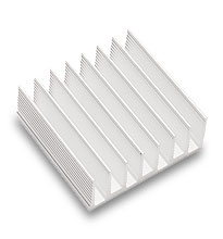
0.40″ longitudinal fins, threaded mounting* | 32188 | PDF | DXF | ||||||||
| 0.90″ longitudinal fins, threaded mounting* | 30189 | PDF | DXF | |||||||||
|
|
|||||||||||
 |
0.40″ longitudinal fins, thru-hole mounting | 30195 | PDF | DXF | ||||||||
| 0.90″ longitudinal fins, thru-hole mounting | 30182 | PDF | DXF | |||||||||
|
|
|||||||||||
 |
0.40″ transverse fins, threaded mounting* | 30184 | PDF | DXF | ||||||||
| 0.90″ transverse fins, threaded mounting | 30269 | PDF | DXF | |||||||||
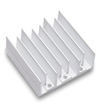 |
0.40″ transverse fins, thru-hole mounting | 30721 | PDF | DXF | ||||||||
| 0.90″ transverse fins, thru-hole mounting | 30724 | PDF | DXF | |||||||||
| * NOT for use with threaded baseplates | |||||||||||
| Heat Sink Thermal Data and Calculator | |||||||||||
| Low-Profile Side-Fin Heat Sinks (Height only 0.125″ above module baseplate) | |||||||||||
| Description | P/N | RoHS | Technical Drawing | ||||||||
|
|
|||||||||||
 |
0.55″ Side-Fin Heat Sink for Mini-Sized Modules | 32190 | |||||||||
| Heat Sink Thermal Data and Calculator | |||||||||||
| ThermMate Thermal Pads (10 pieces per package) | |||||||||||
| Description | P/N | Thickness | RoHS | Technical Drawing | |||||||
 |
For use with Vicor Mini-size modules* | 20264 | 0.007″ | PDF | DXF | |||||||
| * NOT for use with VI-200 or VI-J00 modules | |||||||||||