
Description
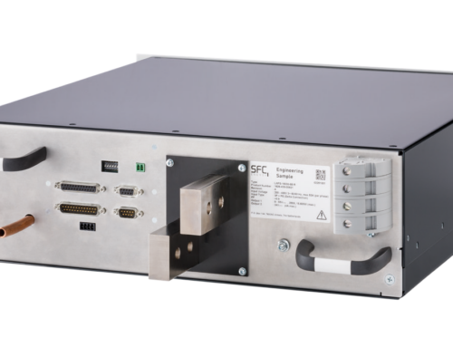
The XZ family of low noise medically approved power supplies provides up to 1200W in an extremely compact 1U x 260 x 127mm package. Boasting industry leading power density of 15W/in3 and efficiencies of up to 90%, the XZ family employs an innovative plug & play architecture that allows users to instantly configure a custom power solution in less than 5 minutes!
Ideal for acoustic sensitive medical applications the XZ family provides unmatched efficiency and high power density, made possible through the combination of low loss technologies and the best field-proven technologies in planar magnetics and surface mount electronics.
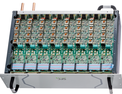
The XZ family consists of 3 powerPac models ranging in power levels from 400W to 1200W. Each model may be populated with up to 6 powerMods selected from the table of powerMods shown below.
All configurations carry full safety agency approvals, UL2601-1, EN60601-1 and are CE marked.
NEW Conformal Coated
-
-
- The Xgen series is now available with conformal coating for protection against harsh environments. The conformal coated Xgen is IP50 rated with protection against dust-and also protected against vertical falling drops of water and non condensing moisture. The Xgen series of power supplies has also been extensively HALT tested for resistance to shock and vibration and characterised over its extended operating temperature range.
-

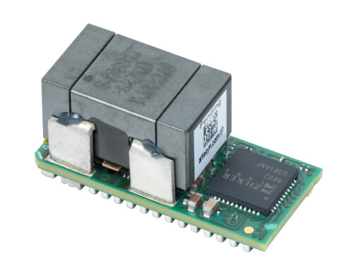
Power Modules for Xgen PowerPacs
Excelsys offers 7 different DC output module for use with Xgen powerPacs to build your custom power supply!
-
-
-
-
- 2.5 Vdc nominal output
- 1.5-3.6 Vdc User adjustable output voltage by potentiometer
- 1.0-3.6 Vdc User adjustable output voltage by Trim-Pin
- 50 A output current
- User adjustable current limit Itrim
- Remote Sense
- Remote ON/OFF
- DC Power Good
-
-
-
-
-
-
-
- 5.0 Vdc nominal output
- 3.2-6.0 Vdc User adjustable output voltage by potentiometer
- 1.5-6.0 Vdc User adjustable output voltage by Trim-Pin
- 40 A output current
- User adjustable current limit Itrim
- Remote Sense
- Remote ON/OFF
- DC Power Good
-
-
-
-
-
-
-
- 12.0 Vdc nominal output
- 6.0-15.0 Vdc User adjustable output voltage by potentiometer
- 4.0-15.0 Vdc User adjustable output voltage by Trim-Pin
- 20 A output current
- User adjustable current limit Itrim
- Remote Sense
- Remote ON/OFF
- DC Power Good
-
-
-
-
-
-
-
- 24.0 Vdc nominal output
- 12.0-30.0 Vdc User adjustable output voltage by potentiometer
- 8.0-30.0 Vdc User adjustable output voltage by Trim-Pin
- 10 A output current
- User adjustable current limit Itrim
- Remote Sense
- Remote ON/OFF
- DC Power Good
-
-
-
-
-
-
-
- 48.0 Vdc nominal output
- 24.0-58.0 Vdc User adjustable output voltage by potentiometer
- 8.0-58.0 Vdc User adjustable output voltage by Trim-Pin
- 6 A output current
- User adjustable current limit Itrim
- Remote Sense
- Remote ON/OFF
- DC Power Good
-
-
-
-
-
-
-
- 24.0 Vdc nominal output
- 5.0-28.0 Vdc User adjustable output voltage by potentiometer
- 5.0-28.0 Vdc User adjustable output voltage by Trim-Pin
- 5 A output current
- Remote ON/OFF
- DC Power Good
-
-
-
-
-
-
-
- 2x 24.0 Vdc nominal output
- 2x 5.0-28.0 Vdc User adjustable output voltage by potentiometer
- 2x 5.0-28.0 Vdc User adjustable output voltage by Trim-Pin
- 2x 3 A output current
- Remote ON/OFF
- DC Power Good
-
-
-
Downloads & Technical Support
-
-
-
-
-
-
-
- Design consultancy support, including product recommendations, to deliver optimal system performance, and importantly reducing time-to-market
- Attention to total cost of ownership for duration of product lifetime — addressed at the design stage
- In-life product support enabling product modifications and upgrades with minimum disruption
- Pre-launch product certification support for the latest standards including; UL, CE, VDE etc
- Management of relationships with key Technical Partners including the worlds leading LED manufacturers
- Publication of white papers outlining the latest Industry, Application and Product trends
-
-
-
-
-
-
-
- Application Note 1103: Remote sensing: Advantages and Implementation
- Application Note 1104: Xgen Power supply features: Adavntages
- Application Note 1105: Ripple & Noise: Measurement and reduction techniques
- Application Note 1106: EMI: Considerations and measurements
- Application Note 1102: Safety: Class I versus Class II
- Application Note 1110: Temperature measurements: Case versus ambient Temperature
- Application Note 1109: Use of planar magnetics: Design and optimisation
- Application Note 1111: HI-POT amd 4KV isolation testing
- Application Note 1108: Regulation of harmonics: EN61000-3-2
- Application Note 1202: Low leakage current Xgen
- Application Note 1301: Thermal management on Power Supplies
- Application Note 1302: Reinforced isolation testing on a power supply
- Application Note 1304: Low leakage medical power supplies
- Application Note 1305: Using the Xgen platform as a constant current source
- Application Note 1306: Paralleling of PowerMods
- Application Note 1307: Designing for a ruggedized Environment
- Application Note 1308: Using the Xgen and Ultimod platform in harsh envirnonments and the use of conformal coating
- Application Note 1309: Methods of protection, MOOPs and MOPPs
- Application Note 1401: SEMI F47-0706: Specification for semiconductor processing equipment voltage sag immunity
- Methods of Protection, MOOPs and MOPS
-
-
-
-
-
-
-
- Power Supply Efficiency White Paper
- Ripple & Noise: Measurement and reduction techniques
- EMI: Considerations and measurement
- Safety: Class I versus Class II
- Temperature Measurements: Case Versus Ambient Temperature
- Planar Magnetics Design
- Shrinking a power supply and the challenge to maintain high reliability
- Designing for a medical application: Choosing the right power partner
-
-
-
The Xgen Designers’ Manual has been prepare by Excelsys power supply experts to assist engineers and technicians in understanding correct design practices necessary to achieve the maximum versatility and performance from any of the Xgen series of family of products. Whatever your application, be it industrial electronics, medical equipment, automation equipment etc., the Xgen Designers’ Manual provides the system designer with easy to implement integration instructions.At Excelsys our background is in the development and support of high efficiency, high reliability Power Supplies for applications in the Medical, Industrial, Lighting and Military markets. We have a long history of working with Market-leading, Blue-Chip Companies, supporting thousands of different Projects and Applications, building up a wealth of both system and product knowledge. Our experienced Applications Teams are based in the US and in Europe allowing them to offer an immediate value add service to our customers.
Key support functions include:
Downloads
Whatever your application, Excelsys can provide a solution. All our power supplies carry full international safety agency approvals including UL and EN for Information Technology and Medical power supplies for the Xgen as well as UL8750 and EN61347-1 for Lighting To ease the system safety approvals we have provide our UL and CB certificates we have also included our Declarations of Conformity.UL Certificates
CB Certificates
Declaration of Conformity
RoHS Declaration Xgen Series
Excelsys power supplies are component power supplies, and as such are not subject to the EMC directive for EMI, however in order to ease system integration, Excelsys Technlogies has carried out extensive EMI characterization of our products against the relevant standards. Our full EMI reports are available.Poor reliability, low MTBF, frequent field returns, high in-warranty costs, and customer dissatisfaction are often the result of design and/or process weaknesses, even if a product has successfully passed qualification tests and burn-in. Excelsys Technologies subjects all our products to the HALT (Highly Accelerated Life Testing) process to uncover design and/or process weaknesses. During the HALT process, the product is subjected to progressively higher stress levels brought on by thermal dwells, vibration, rapid temperature transitions and combined environments. These stimuli are well beyond the expected operating field environments HALT Test report Xgen Series.Excelsys power supply experts have an extensive knowledge of power supplies, technology and the challenges facing system designers. In conjunction with the Xgen Designers’ Manual, and Application Notes, we also prepare White Papers on topics that are relevant to system designers.Downloads
Q: Can I create a negative output from the Xgen?
A: Yes. All outputs in the Xgen are fully isolated outputs, so they can be referenced to a common point creating either a positive or negative output voltage. To create a negative 5V output for example, the +Vout terminal of the module should be connected to the common return (chassis ground, earth ground etc). The –Vout terminal will then deliver the -5V output. All outputs have 500V output-output isolation and 500V output-ground isolation.Q: Can I connect 2 or more power supplies in parallel for higher current?
A: Yes. The Xgen series of power supplies can be parallel connected for higher power and current applications. The maximum Earth Leakage Current of the system is an important consideration for the system designer. Depending on the application, this figure will vary, for example in industrial equipment it is 3.5mA. The total leakage current from the power supplies should be calculated by adding the individual Maximum Earth Leakage of each power supply. E.g. 6 x XVD (each with maximum Earth Leakage of 300uA) will have a combined maximum Earth Leakage of 1.8mA. Earth Leakage current will vary with input line voltage. It is higher a 220VAC than 110VAC. Excelsys Technologies measures Earth Leakage at the worst case voltage of 250VAC. It is also important to note that other components in the system can contribute to Earth Leakage current and should be considered when calculating the maximum system Earth Leakage current.Q: Can I use an Xgen in my Medical Equipment?
A: Yes. The Xmite, Xrite, Xvite and Xzite provide medically approved power supplies from 200W to 1340W. Our medically approved power supplies are CE marked for Safety and carry full EN60601-1 approvals meeting 4000KV isolation,less than 300uA Earth Leakage current and required creepage and clearances. Certificates and reports are available in our Technical Support section. For more details on medical power supplies, implementation and considerations, please visit our Medical Electronics section and our Application Notes section.Q: Are Excelsys products RoHS compliant?
A: Yes. All Excelsys products meet the requirements of the RoHS (Reduction of Hazardous Substances) Directive. Our program of compliance was completed in 2006. The WEEE (Waste Electrical and Electronic Equipment) Directive covers a number of items including; large and small household appliances, Electric and Electronic tools, lighting and consumer equipment. Excelsys Technologies can confirm that our power supplies do not fall under the scope of the WEEE Directive. Note that some power supplies do fall under the scope of the WEEE Directive such as External power supplies.Q: Can I remotely switch ON/OFF the Xgen?
A: Yes. The Xgen has global Inhibit/Enable function built in that allows users to remotely switch ON/OFF the power supply using a digital or analog signal. Furthermore, each of the isolated outputs can also be individually Inhibited/Enabled allowing users to sequence outputs and control their system start-up. For more details on how to implement these functions, please refer to the Xgen Designers Manual.Q: Can I parallel connect power supplies for an N+1 redundancy system?
A: Yes. Parallel connecting powers supplies for operation in Redundant mode is an acceptable and often necessary practise for mission critical applications. To ensure correct operation each power supply must be capable of providing the full system load. The the power supplies should have their outputs connected in parallel via diodes. The diodes permit on power supply to fail without affecting the other. For more details see our Xgen Designers Manual and Application Notes section.Q: I have a number of PowerMods in parallel and want to use the remote sense option, do I need to bring out all of the sense lines to my load?
A: All of the sense lines will need to be connected to the load, but the complexity of the wiring can be reduced by connecting all of the sense lines locally and bringing out one pair of sense lines to the load. Please refer to the designer’s manual for more details on this.Q: I notice the Xg8 is a dual output, if I have an unbalanced load will it affect cross regulation?
A: No. Both outputs are fully floating and are isolated from each other. They also both have independent regulation which is not effected by the adjacent output.Q: I notice that when I connect the sense pins the output voltage drops, even at no load. Is this that you would expect?
A: Yes. Due to the voltage ratio of our feedback divider chain when the sense lines are connected we would expect to see approx 200mV drop once the remote sense lines are connected.Q: I have a battery charging application; do you recommend the use of a blocking diode?
A: The Xgen is designed to sink and source current in order to maintain its regulation set point. We also have a negative current limit to prevent damage to the freewheel fet in the event of excessive energy coming back form the load. In a battery charging application, where this energy is sufficiently high there is a possibility that this may be a source for potential damage, so Excelsys would always recommend a blocking diode for any battery charging application.Q: Can I use a combination of units in parallel AND in series to give me my required voltage and power requirements?
A: Yes. The Xgen series is the most flexible power supply on the marketQ: Where is the voltage setpoint measured on a configured Xgen?
A: For powerMods Xg1 to Xg5 the output voltage is set at the positive and negative sense pins, i.e. Pin1 and Pin 2 of Connector J3. For powerMod Xg7 the output is set at the +Vout (Pin2) and -Vout (Pin 1) of the J4 connector. For powerMod Xg8 the output is set on the +Vout and -Vout pins for each output, i.e. Pin 4 through to Pin1 respectively of the connector J4.Q: Are the fans always on and are they constant speed?
A: Yes. The Xgen powerPac consists of a fan cooled semi-enclosed chassis. An always-on consent speed fan is used to enable industry leading power densities of 15W/in3 and the 90% plus efficiencies up to the 1340Watts available. To increase fan life the Global Inhibit can be used to turn off the power supply under no load conditions (fan will be turned off) and for acoustic sensitive applications the Xgen series is available in a Low Acoustic Noise versions.Q: Can I use a DC input voltage with the Xgen series?
A: Yes. As well as universal input voltage range from 85 to 264VAC the Xgen also works with 120 to 380VDC at the input.Q: How do I set the voltage on individual powerMods when they are being used in parallel ?
A: First ensure that the powerMods DIPswitch I Share is set to ON for reach powerMod. Then attach the negative parallel link. Adjust the output voltage on powerMod1 to the required output. Measure the voltage difference between the positive terminals of powerMod 1 and power mod 2. Adjust the powerMod 2 voltage to minimize the delta and then attach the positive parallel links. Repeat this for each subsequent powerMod. Full details of this are provided in the powerMod Operation in Section 7 of the Xgen Designers Manual.Q: Is the OVP (Over Voltage protection) latching or non latching ?
A: Overvoltage protection (OVP) is implemented as a two level scheme. Level One OVP is initiated when the output is between 110 to 115% of the Vset, this is non latching. Level Two OVP fixed relative to Vmax. If the output voltage rises to between 110 to 125% of Vmax the OVP is initiated. This is a latching protection and it is reset by removing and reinstating the input power. Full details of all the protection features of the Xgen series are given in Section 7 of the Designers Manual. -
-
-