
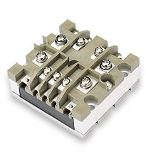
The MI-AIM AC input module interfaces directly with AC mains to provide line rectification, EMI filtering, transient protection, and inrush limiting. These front-end modules accept 115 Vac and provide 250 W of output power for any of Vicor’s MI-x7x family of full-brick and half-brick sized modules.
The MI-AIM meets CE102 conducted emissions requirements of MIL-STD-461D/E, the transient and spike requirements of MIL-STD-704A, and the environmental test requirements of MIL-STD-810.
Universal Input:
- 115 Vac; 60/400 Hz
Output Power(per module):
- 250 W
Output Voltage:
- Rectified Line
- 1 – 95 Vdc (with MI-x7x DC-DC converters)
Efficiency:
- Up to 95%
Dimensions(half brick):
- 2.28″ x 2.4″ x 0.5″ (57,9 x 61,0 x 12,7 mm)
Operating Temperature:
- -55°C to 100°C M-Grade
- Compatible with Vicor MI-x7x family of modules
- Inrush limiting
- MIL-STD-461D/E CE102 compliance for conducted emissions
- MIL-STD-704A compliance for input transients
- MIL-STD-810 environments compliance
- Environmental stress screening
Download Entire Manual
Download Individual Chapters
- Zero-Current Switching
- DC-DC Converter Pinouts
- Module Dos and Donts
- Overcurrent Protection
- Output Voltage Trimming
- Multiple Gate In Connections
- Applications Circuits / Converter Array Design Considerations
- Using Boosters and Parallel Arrays
- EMC Considerations
- Optional Output Filters
- Battery Charger (BatMod)
Filter and Front-End Module Chapters
- AC Input Module (AIM / MI-AIM)
- Harmonic Attenuator Module (HAM)
- Input Attenuator Module (IAM / MI-IAM)
- Ripple Attenuator Module (RAM / MI-RAM)
- Offline Front End
Power System Chapters
- DC Input Power System (ComPAC / MI-ComPAC Family)
- AC Input Power System (FlatPAC Family)
- AC Input Power System (PFC FlatPAC)
General Chapters
| Description | P/N | Capacitance | Voltage Rating | RoHS | Technical Drawing | ||||||
| Capacitors | |||||||||||
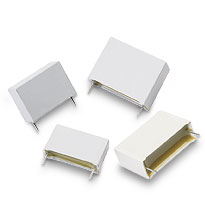 |
X-Cap | 03047 | 0.47 µF | 250 Vac | PDF | – | ||||||
 |
Y-Cap | 01000 | 4,700 pF | 250 Vac | PDF | – | ||||||
| Y-Cap | 03285 | 4,700 pF | 250 Vac | PDF | – | |||||||
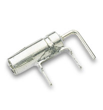
| Y-Cap Surface Mount | 25283 | 4,700 pF | 250 Vac | PDF | – | |||||||
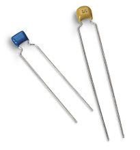 |
Ceramic | 28054 | 0.01 µF | 500 V | PDF | – | ||||||
| Ceramic | 30458 | 470 pF | 500 V | PDF | – | |||||||
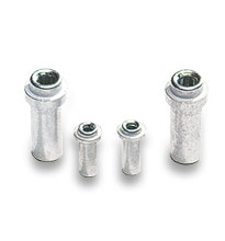
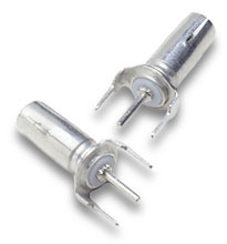
 |
Holdup | 30240 | 270 µF | 400 V | PDF | – | ||||||
| Holdup | 30249 | 470 µF | 450 V | PDF | DXF | |||||||
| Holdup | 30769 | 270 µF | 200 V | PDF | – | |||||||
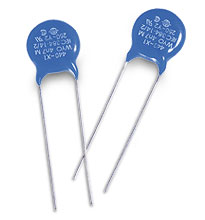
| MOVs | |||||||||||
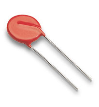 |
14 mm Disc | 30076 | 275 V | PDF | – | |||||||

| Description | P/N | Capacitance | Height of HUB | RoHS | Technical Drawing | ||||||
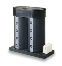 |
Holdup Box | HUB270-P | 270 µF | 1.75″ | PDF | DXF | ||||||
| Holdup Box | HUB470-P | 470 µF | 2.34″ | PDF | DXF | |||||||
| Holdup Box | HUB820-P | 820 µF | 3.52″ | PDF | DXF | |||||||
| HUB contains two (2) capacitors of the value shown. | |||||||||||
| Mounting Connector Kit | |||||||||||
| Kit includes one connector and pins | 21395 | – | |||||||||

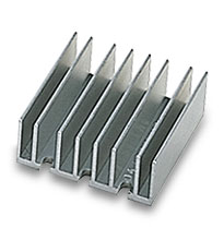
| Heat sinks used with Vicor’s VI-J00-size module (not Mini modules) | ||||||||
| Description | P/N | RoHS | Technical Drawing | |||||
 |
0.90″ Longitudinal Fins | 30191 | PDF | DXF | |||||
 |
0.90″ Transverse Fins | 30771 | PDF | DXF | |||||
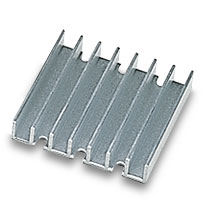 |
0.40″ Transverse Fins | 30140 | PDF | DXF | |||||
| Heat Sink Thermal Data and Calculator | ||||||||
| ThermMate Thermal Pads (10 pieces per package) | ||||||||
| Description | Thickness | P/N | RoHS | Technical Drawing | ||||
 |
For use with Vicor VI-J00 moduels only (not Mini modules) |
0.007″ | 20267 | PDF | DXF | ||||
| Grounding Clips | ||||||||
| Description | P/N | RoHS | Technical Drawing | |||||
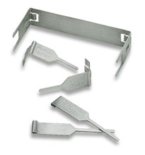 |
For use with FinMod, Longitudinal 0.25″ Fins (-F1) | 32185 | PDF | DXF | |||||
| For use with FinMod, Longitudinal 0.50″ Fins (-F2) | 32185 | PDF | DXF | ||||||
| For use with FinMod, Transverse 0.25″ Fins (-F3) | 32186 | PDF | DXF | ||||||
| For use with FinMod, Transverse 0.50″ Fins (-F4) | 32186 | PDF | DXF | ||||||
| For use with SlimMod Flangless package (-S) | 32187 | PDF | DXF | ||||||