
Vicor’s Maxi, Mini and Micro family of DC-DC converters provides high power density and low noise, with advanced power processing in a robust package. The converters are compact and efficient, and offer several input ranges, a variety of output voltages, enhanced output programmability, remote sense, and single-wire paralleling for high power or for true redundant operation. The efficiency and packaging design simplify thermal management with baseplate operation up to 100°C. The modules are available with five temperature grades, three baseplate styles, and six pin types.
Maxi, Mini and Micro product series technology allows for the automated generation of user-defined designs without the customary long lead times typical of custom designs.
- 24 V (18 – 36 V)
- 28 V (9 – 36 V)
- 48 V (36 – 75 V)
- 72 V (43 – 110 V)
- 110 V (66 – 154 V)
- 150 V (100 – 200 V)
- 300 V (180-375 V)
- 375 V (250-425 V)
- 2 – 54 Vdc
- Maxi: 160 – 600 W
- Mini: 100 – 300 W
- Micro: 50 – 150 W
- Up to 90%
- Maxi (full brick): 4.6″ x 2.2″ x 0.5″(117 x 55,9 x 12,7 mm)
- Mini (half brick): 2.28″ x 2.2″ x 0.5″(57,9 x 55,9 x 12,7 mm)
- Micro (quarter brick): 2.28″ x 1.45″ x 0.5″ (57,9 x 36,8 x 12,7 mm)
- Robust packaging for harsh environments
- Extended temperature range (-55 to 100°C)
- Up to 120 W/in3
- Low noise zero-current switching and zero-voltage switching technology
- Single-wire paralleling
- Output voltage adjusts from 10-110%
- Logic enable / disable
- Input undervoltage lockout
- Output overvoltage protection
- Overtemperature shutdown
To view individual family data sheets for available intermediate power levels, click on the links.
Note: All power values are in Watts
* The 375 Vdc Maxi module is also available in output voltages of 32 V and 54 V @ 600 W
- Thermal Considerations: Assuring Density DC-DC Converter Modules
- Designing High-Power Arrays using Maxi, Mini, Micro Family DC-DC Converters
- Component Power Solutions for Industrial High Voltage Applications
- Wide Range Trimming with Variable Loads
- High Efficiency Battery Charger Using Power Components
- Using Modular DC-DC Converters to Meet European Standards for Railway Applications
- Adjustable Latching Output Over Current Circuit
- Hot Swap Capability Eliminates Downtime
- Converter PR Pin Facilitates Parallel Operation forPerformance of Maxi, Mini and Micro High- Power Expansion or Redundancy
- Soldering Methods and Procedures for Vicor Power Modules
- Constant Current Control for DC-DC Converters
- Creating High Voltage Outputs
- High Density DC-DC Converter Technology
- Control Pin Functions and Applications
- Design Requirements
- EMC Considerations
- Current Sharing in Power Arrays
- Thermal Performance Information
Accessory Modules
- Autoranging Rectifier Module (ARM)
- Filter / Autoranging Rectifier Module (FARM)
- Modular AC Front-end System (ENMod)
- High Boost HAM
- Filter Input Attenuator Module (FIAM)
- Output Ripple Attenuator Module (MicroRAM)
Recommended Soldering Methods
Mounting Options
- cURus – UL 60950-1, CSA 60950-1
- cTÜVus – EN 60950-1, UL 60950-1, CSA 60950-1
- CE Marked – Low Voltage Directive (2006/95/EC)
- CB Certificate – IEC 60950-1:2001
- Module Safety Instruction Sheet
Maxi – Size
| 2-D Maxi-size Drawings | |||
| Drwg. Number | Description | Download | RoHS |
| 37205 | Outline drawing for Maxi DC-DC Converter | DXF | PDF | |
| 3-D Maxi-size Module (referring to drawing number 37205) | |||
| Maxi, short tin / lead pin, slotted baseplate | STEP | 3D PDF | ||
| Maxi, short tin / lead pin, threaded baseplate | STEP | 3D PDF | ||
| Maxi, short tin / lead pin, through-hole baseplate | STEP | 3D PDF | ||
| Maxi, long tin / lead pin, slotted baseplate | STEP | 3D PDF | ||
| Maxi, long tin / lead pin, threaded baseplate | STEP | 3D PDF | ||
| Maxi, long tin / lead pin, through-hole baseplate | STEP | 3D PDF | ||
| Maxi, short ModuMate, slotted baseplate | STEP | 3D PDF | ||
| Maxi, short ModuMate, threaded baseplate | STEP | 3D PDF | ||
| Maxi, short ModuMate, through-hole baseplate | STEP | 3D PDF | ||
| Maxi, long ModuMate, slotted baseplate | STEP | 3D PDF | ||
| Maxi, long ModuMate, threaded baseplate | STEP | 3D PDF | ||
| Maxi, long ModuMate, through-hole baseplate | STEP | 3D PDF | ||
| Maxi, short gold pin (RoHS), slotted baseplate | STEP | 3D PDF | ||
| Maxi, short gold pin (RoHS), threaded baseplate | STEP | 3D PDF | ||
| Maxi, short gold pin (RoHS), through-hole baseplate | STEP | 3D PDF | ||
| Maxi, long gold pin (RoHS), slotted baseplate | STEP | 3D PDF | ||
| Maxi, long gold pin (RoHS), threaded baseplate | STEP | 3D PDF | ||
| Maxi, long gold pin (RoHS), through-hole baseplate | STEP | 3D PDF | ||
Mini – Size
| 2-D Mini-size Drawings | |||
| Drwg. Number | Description | Download | RoHS |
| 37206 | Outline drawing for Mini DC-DC Converter | DXF | PDF | |
| 3-D Mini-size Module (referring to drawing number 37206) | |||
| Mini, short tin / lead pin, slotted baseplate | STEP | 3D PDF | ||
| Mini, short tin / lead pin, threaded baseplate | STEP | 3D PDF | ||
| Mini, short tin / lead pin, through-hole baseplate | STEP | 3D PDF | ||
| Mini, long tin / lead pin, slotted baseplate | STEP | 3D PDF | ||
| Mini, long tin / lead pin, threaded baseplate | STEP | 3D PDF | ||
| Mini, long tin / lead pin, through-hole baseplate | STEP | 3D PDF | ||
| Mini, short ModuMate, slotted baseplate | STEP | 3D PDF | ||
| Mini, short ModuMate, threaded baseplate | STEP | 3D PDF | ||
| Mini, short ModuMate, through-hole baseplate | STEP | 3D PDF | ||
| Mini, long ModuMate, slotted baseplate | STEP | 3D PDF | ||
| Mini, long ModuMate, threaded baseplate | STEP | 3D PDF | ||
| Mini, long ModuMate, through-hole baseplate | STEP | 3D PDF | ||
| Mini, short gold pin (RoHS), slotted baseplate | STEP | 3D PDF | ||
| Mini, short gold pin (RoHS), threaded baseplate | STEP | 3D PDF | ||
| Mini, short gold pin (RoHS), through-hole baseplate | STEP | 3D PDF | ||
| Mini, long gold pin (RoHS), slotted baseplate | STEP | 3D PDF | ||
| Mini, long gold pin (RoHS), threaded baseplate | STEP | 3D PDF | ||
| Mini, long gold pin (RoHS), through-hole baseplate | STEP | 3D PDF | ||
Micro – Size
| 2-D Micro-size Drawings | |||
| Drwg. Number | Description | Download | RoHS |
| 37207 | Outline drawing for Micro DC-DC Converter | DXF | PDF | |
| 3-D Micro-size Module (referring to drawing number 37207) | |||
| Micro, short tin / lead pin, slotted baseplate | STEP | 3D PDF | ||
| Micro, short tin / lead pin, threaded baseplate | STEP | 3D PDF | ||
| Micro, short tin / lead pin, through-hole baseplate | STEP | 3D PDF | ||
| Micro, long tin / lead pin, slotted baseplate | STEP | 3D PDF | ||
| Micro, long tin / lead pin, threaded baseplate | STEP | 3D PDF | ||
| Micro, long tin / lead pin, through-hole baseplate | STEP | 3D PDF | ||
| Micro, short ModuMate, slotted baseplate | STEP | 3D PDF | ||
| Micro, short ModuMate, threaded baseplate | STEP | 3D PDF | ||
| Micro, short ModuMate, through-hole baseplate | STEP | 3D PDF | ||
| Micro, long ModuMate, slotted baseplate | STEP | 3D PDF | ||
| Micro, long ModuMate, threaded baseplate | STEP | 3D PDF | ||
| Micro, long ModuMate, through-hole baseplate | STEP | 3D PDF | ||
| Micro, short gold pin (RoHS), slotted baseplate | STEP | 3D PDF | ||
| Micro, short gold pin (RoHS), threaded baseplate | STEP | 3D PDF | ||
| Micro, short gold pin (RoHS), through-hole baseplate | STEP | 3D PDF | ||
| Micro, long gold pin (RoHS), slotted baseplate | STEP | 3D PDF | ||
| Micro, long gold pin (RoHS), threaded baseplate | STEP | 3D PDF | ||
| Micro, long gold pin (RoHS), through-hole baseplate | STEP | 3D PDF | ||
This is a downloadable Excel file.

- FIAM – Filter Input Attenuator Module – DC input, front-end module providing transient protection, inrush current limiting and EMI filtering for Maxi, Mini and Mico DC-DC converters.
- QPI Family Input Filters – QPIs provide common mode and differential mode attenuation from 150 kHz to 30 MHz in a 1.0″ x 1.0″ (25 x 25 mm) surface mount package.
- MicroRAM – Output Ripple Attenuator Module – The MicroRAM combines both active and passive filtering to achieve greater than 40 dB of noise attenuation from over a range of 3 to 30 Vdc.
- QPO Family Output Filters – QPO filters use active filtering to reduce power supply ripple and noise in a 1.0″ x 1.0″ (25 x 25 mm) surface mount package.
- ARM – Autoranging Rectifier Module – The ARM is the front end of a switching power supply and uses a microprocessor to control strapping of the voltage doubler.
- FARM – Filter / Autoranging Rectifier Module – The FARM is an AC front-end module which provides EMI filtering, autoranging line rectification and inrush current limiting.
- ENMods – Modular AC Front-end System – The ENMods system combines EMI filtering with the FARM and MiniHAM modules creating an AC front end fully compliant with European norms for harmonic current limits, EMI and input transient immunity.
- High Boost HAM – AC Harmonic Attenuator Module – The HAM module is a full-wave rectifier with a high-frequency zero-current switching (ZCS) boost converter providing up to 675 Watts of power in a full-brick package.
| Description | P/N | Capacitance | Voltage Rating | RoHS | Technical Drawing | ||||||
 |
SMT Polymer | 23484-337 | 330 µF | 6.3 V | PDF | DXF | ||||||
| SMT Polymer | 23484-477 | 470 µF | 6.3 V | PDF | DXF | |||||||
| SMT Polymer | 23579-227 | 220 µF | 10 V | PDF | DXF | |||||||
 |
Al-El (10 mm x 16 mm) | 30468 | 270 µF | 25 V | |||||||
| Al-El (16 mm x 15 mm) | 33985 | 820 µF | 25 V | ||||||||
| Al-El (10 mm x 16 mm) | 30788 | 68 µF | 63 V | ||||||||
| Al-El (10 mm x 16 mm) | 30787 | 220 µF | 63 V | ||||||||
| Al-El (10 mm x 50 mm) | 34837-108 | 10 µF | 63 V | ||||||||
 |
Tantalum | 30800 | 270 µF | 10 V | |||||||
| Tantalum | 30506 | 120 µF | 20 V | ||||||||
| Tantalum | 30507 | 68 µF | 30 V | ||||||||
| Tantalum | 30259 | 27 µF | 50 V | ||||||||
|
X-Capacitor | 04068 | 0.22 µF | 250 Vac | |||||||
| X Capacitor | 03047 | 0.47 µF | 250 Vac | ||||||||
| X Capacitor | 02573 | 1 µF | 250 V | ||||||||
| X Capacitor | 03269 | 0.15 µF | 310 V | ||||||||
| X Capacitor | 00927 | 0.33 µF | 275 V | ||||||||
 |
Y-Cap Surface Mount | 25283 | 4,700 pF | 250 Vac | |||||||
| Y-Cap | 03285 | 4,700 pF | 250 Vac | ||||||||
| Y-Cap | 30802 | 1,500 pF | 250 V | ||||||||
| Y-Cap | 00770 | 1,500 pF | 250 Vac | PDF | DXF | |||||||
| Y-Cap | 01000 | 4,700 pF | 250 Vac | ||||||||
| Y-Cap | 33643 | 0.01 µF | 250 V | ||||||||
| Y-Cap | 03093 | 0.022 µF | 250 V | ||||||||
| Multilayer Film Cap | 34610 | 0.61 µF | 250 V | PDF | DXF | |||||||
| Ceramic Capacitors | 28054 | 0.01 µF | 500 V | ||||||||
| Ceramic Capacitors | 30458 | 470 pF | 500 V | ||||||||
| Holdup Capacitors | 30240 | 270 µF | 400 Vac | ||||||||
| Holdup Capacitors | 30249 | 470 µF | 450 Vac | ||||||||
| Holdup Capacitors | 30769 | 270 µF | 200 Vac | ||||||||
| Description | P/N | RoHS | Technical Drawing | |||||||
 |
Maxi Shield for Slotted Baseplate | 30199 | PDF | DXF | |||||||
| Mini Shield for Slotted Baseplate | 30198 | PDF | DXF | ||||||||
| Micro Shield for Slotted Baseplate | 30141 | PDF | DXF | ||||||||
| Maxi Shield for Threaded or Through-Hole Baseplate | 30142 | PDF | DXF | ||||||||
| Mini Shield for Threaded or Through-Hole Baseplate | 30180 | PDF | DXF | ||||||||
| Micro Shield for Threaded or Through-Hole Baseplate | 30143 | PDF | DXF | ||||||||
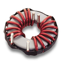
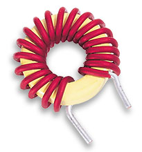
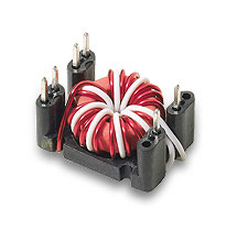
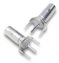
| Common Mode | ||||||||||||
| Description | P/N | Inductance | Rated Current | DCR(max) | RoHS | Technical Drawing | ||||||
 |
Common-mode input | 31743 | 1,000 µH | 12 A | 6.5 mΩ | PDF | DXF | ||||||
| Common-mode input | 32006 | 1,300 µH | 13 A | 14 mΩ | PDF | DXF | |||||||
| Common-mode input | 31943 | 2,163 µH | 1 A | 42 mΩ | PDF | DXF | |||||||
| Common-mode input | 31742 | 3,000 µH | 7 A | 18 mΩ | PDF | DXF | |||||||
 |
Common-mode output | 36-00029-06 | 70 µH | 80 A | 0.4 mΩ | |||||||
| Common-mode output | 36-00029-07 | 110 µH | 60 A | 0.6 mΩ | ||||||||
| Common-mode output | 36-00029-01 | 335 µH | 40 A | 2 mΩ | PDF | DXF | |||||||
| Common-mode output | 36-00037 | 420 µH | 20 A | 5 mΩ | ||||||||
| Common-mode output | 36-00029-04 | 1,270 µH | 10 A | 10 mΩ | PDF | DXF | |||||||
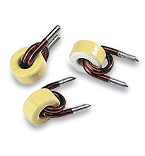
| Differential Mode | ||||||||||||
 |
Differential-mode input | 33206 | 22 µH | 12 A | 5.5 mΩ | PDF | DXF | ||||||
| Differential-mode input | 36-00036 | 1,000 µH | 4 A | 250 mΩ | ||||||||
|
|
||||||||||||
 |
Differential-mode output | 30268 | 0.2 µH | 40 A | – | PDF | DXF | ||||||
| Differential-mode output | 32012 | 27 µH | 12 A | – | ||||||||
| Differential-mode output | 32497 | 1.8 µH | 10 A | – | PDF | DXF | |||||||
| Output-sense compensation | 36-00030 | 1,000 µH | – | – | ||||||||
| Surface Mount | Download Surface-Mount Inductor Data Sheet | |||||||||||
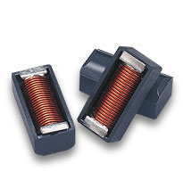 |
Surface-mount inductor | 31499-16 | 0.37 µH | 100 A | 0.23 mΩ | PDF | DXF | ||||||
| Surface-mount inductor | 31499-15> | 0.66 µH | 75 A | 0.42 mΩ | PDF | DXF | |||||||
| Surface-mount inductor | 31499-14 | 1.03 µH | 60 A | 0.58 mΩ | PDF | DXF | |||||||
| Surface-mount inductor | 31499-13 | 1.48 µH | 50 A | 0.82 mΩ | PDF | DXF | |||||||
| Surface-mount inductor | 31499-12 | 2.62 µH | 37.5 A | 1.43 mΩ | PDF | DXF | |||||||
| Surface-mount inductor | 31499-10 | 5.90 µH | 25 A | 3.23 mΩ | PDF | DXF | |||||||
| Surface-mount inductor | 31499-08 | 13.2 µH | 16.6 A | 7.56 mΩ | PDF | DXF | |||||||
| Surface-mount inductor | 31499-05 | 47.4 µH | 8.8 A | 29.4 mΩ | PDF | DXF | |||||||
| Surface-mount inductor | 31499-03 | 133 µH | 5.6 A | 81.2 mΩ | PDF | DXF | |||||||
| Surface-mount inductor | 31499-02 | 243 µH | 3.9 A | 156 mΩ | PDF | DXF | |||||||
 |
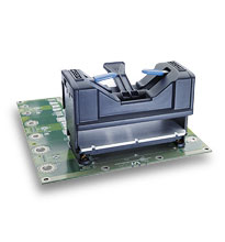
SurfMates – Surface-mount Sockets | All SurfMates are RoHS Compatible | |||||||||||
| Board Thickness | Mounting | Assembly Drawing | Converter Pin Style* | Module Style | InputP/N** | Output P/N** | 5 In/Out Sets P/N | Technical Drawing | |||||
| All | surface | PDF|DXF | F | Maxi | 22100 | 22101 | 16017 | PDF | DXF | |||||
| All | surface | PDF|DXF | F | Mini | 22100 | 22102 | 16021 | PDF | DXF | |||||
| All | surface | PDF|DXF | F | Micro | 22103 | 22104 | 16025 | ||||||
| Example of SurfMate Application | |||||||||||||
| * F = Short Gold (RoHS), G = Long Gold (RoHS)** For individual input / output purchases, a 35-piece minimum (and multiples) applies to Maxis / Minis and a 40-piece minimum (and multiples) for Micros. | |||||||||||||
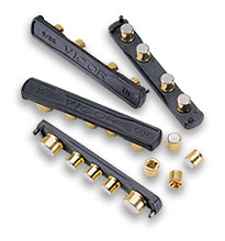 |
InMates – Through-hole | All InMates are RoHS Compatible | |||||||||||
| All sockets are supplied on InMate headers to assure proper alignment during installation. | |||||||||||||
| Board Thickness (nominal) | Board Thickness(min / max) | Mounting | Converter Pin Style* | Module Style | Input P/N** | Output P/N** | 5 In/Out Sets P/N | Technical Drawing | |||||
| 0.063″ | 0.055″ / 0.071″ | inboard | F | Maxi | 18374 | 18382 | 18362 | PDF | DXF | |||||
| 0.063″ | 0.055″ / 0.071″ | inboard | F | Mini | 18374 | 18384 | 18366 | PDF | DXF | |||||
| 0.063″ | 0.055″ / 0.071″ | inboard | F | Micro | 18376 | 18386 | 18370 | PDF | DXF | |||||
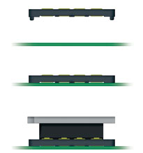
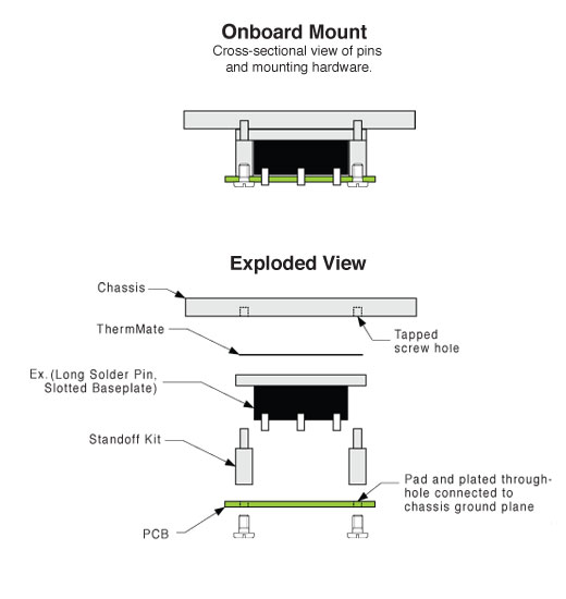
| 0.063″ | 0.055″ / 0.071″ | onboard | G | Maxi | 18378 | 18388 | 18364 | PDF | DXF | |||||
| 0.063″ | 0.055″ / 0.071″ | onboard | G | Mini | 18378 | 18390 | 18368 | PDF | DXF | |||||
| 0.063″ | 0.055″ / 0.071″ | onboard | G | Micro | 18380 | 18392 | 18372 | PDF | DXF | |||||
| 0.094″ | 0.084″ / 0.104″ | inboard | F | Maxi | 18375 | 18383 | 18363 | ||||||
| 0.094″ | 0.084″ / 0.104″ | inboard | F | Mini | 18375 | 18385 | 18367 | ||||||
| 0.094″ | 0.084″ / 0.104″ | inboard | F | Micro | 18377 | 18387 | 18371 | ||||||
| 0.094″ | 0.084″ / 0.104″ | onboard | G | Maxi | 18379 | 18389 | 18365 | ||||||
| 0.094″ | 0.084″ / 0.104″ | onboard | G | Mini | 18379 | 18391 | 18369 | ||||||
| 0.094″ | 0.084″ / 0.104″ | onboard | G | Micro | 18381 | 18393 | 18373 | ||||||
| 0.125″ | 0.1125″ / 0.1375″ | onboard | G | Maxi | 21539 | 21543 | 21510 | ||||||
| 0.125″ | 0.1125″ / 0.1375″ | onboard | G | Mini | 21539 | 21544 | 21511 | ||||||
| 0.125″ | 0.1125″ / 0.1375″ | onboard | G | Micro | 21540 | 21545 | 21512 | ||||||
| Example of Inboard Mounting Options Example of Onboard Mounting Options | |||||||||||||
| * F = Short Gold (RoHS), G = Long Gold (RoHS)** For individual input / output purchases, a 35-piece minimum (and multiples) applies to Maxis / Minis and a 40-piece minimum (and multiples) for Micros. | |||||||||||||
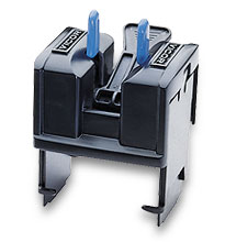
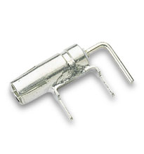
Module Exchange Tools |
|||||||||||||
| Description | Module Style | P/N | Technical Drawing | ||||||||||
 |
Used to facilitate the proper extraction of Maxi modules from InMate or SurfMate sockets. | Maxi | 22827 | — | |||||||||
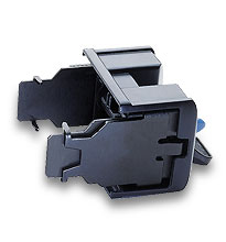 |
Used to facilitate the proper extraction of Mini modules from InMate or SurfMate sockets. | Mini | 22828 | — | |||||||||
 |
Used to facilitate the proper extraction of Micro modules from InMate or SurfMate sockets. | Micro | 22829 | — | |||||||||
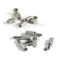 |
Standoff Kits for Solder Mounted Modules | All Standoffs are RoHS Compatible | ||||||||||||||
| Board Thickness | Mounting | Converter Pin Style | Baseplate | Heat Sink | Kit P/N* | Bag P/N** | Technical Drawing | |||||||||
| 0.063″ | inboard | F, Blank | slotted | thru-hole | 18150 | 19126 | PDF | DXF | |||||||||
| 0.063″ | inboard | F, Blank | slotted | threaded | 18151 | 19127 | PDF | DXF | |||||||||
| 0.063″ | inboard | F, Blank | thru-hole | thru-hole | 18146 | 19122 | PDF | DXF | |||||||||
| 0.063″ | inboard | F, Blank | thru-hole | threaded | 18147 | 19123 | PDF | DXF | |||||||||
| 0.063″ | inboard | F, Blank | threaded | thru-hole | 18146 | 19122 | PDF | DXF | |||||||||
| 0.063″ | onboard | G, L | slotted | thru-hole | 18156 | 19132 | PDF | DXF | |||||||||
| 0.063″ | onboard | G, L | slotted | threaded | 18157 | 19133 | PDF | DXF | |||||||||
| 0.063″ | onboard | G, L | thru-hole | thru-hole | 18150 | 19126 | PDF | DXF | |||||||||
| 0.063″ | onboard | G, L | thru-hole | threaded | 18152 | 19128 | PDF | DXF | |||||||||
| 0.063″ | onboard | G, L | threaded | thru-hole | 18150 | 19126 | PDF | DXF | |||||||||
| 0.093″ | inboard | G, L | slotted | thru-hole | 18150 | 19126 | PDF | DXF | |||||||||
| 0.093 “ | inboard | G, L | slotted | threaded | 18151 | 19127 | PDF | DXF | |||||||||
| 0.093 “ | inboard | G, L | thru-hole | thru-hole | 18146 | 19122 | PDF | DXF | |||||||||
| 0.093 “ | inboard | G, L | thru-hole | threaded | 18147> | 19123 | PDF | DXF | |||||||||
| 0.093 “ | inboard | G, L | threaded | thru-hole | 18146 | 19122 | PDF | DXF | |||||||||
| * Kits include six (6) standoffs and screws. Mini and Micro modules require a minimum of four standoffs.** Bags of one hundred (100) do not include screws; #4-40 thread hardware required. | ||||||||||||||||
| Design Information for Solder Mounting | ||||||||||||||||
|
Standoff Kits for InMate Mounted Modules | All Standoffs are RoHS Compatible | ||||||||||||||
| Board Thickness | Mounting | Converter Pin Style | Baseplate | Heat Sink | Kit P/N* | Bag P/N** | Technical Drawing | |||||||||
| 0.063″ | inboard | S | slotted | thru-hole | 18153 | 19129 | PDF | DXF | |||||||||
| 0.063″ | inboard | S | slotted | threaded | 18154 | 19130 | PDF | DXF | |||||||||
| 0.063″ | inboard | S | thru-hole | thru-hole | 18148 | 19124 | PDF | DXF | |||||||||
| 0.063″ | inboard | S | thru-hole | threaded | 18149 | 19125 | PDF | DXF | |||||||||
| 0.063″ | inboard | S | threaded | thru-hole | 18148 | 19124 | PDF | DXF | |||||||||
| 0.063″ | onboard | N | slotted | thru-hole | 18158 | 19134 | PDF | DXF | |||||||||
| 0.063″ | onboard | N | slotted | threaded | 18159 | 19135 | PDF | DXF | |||||||||
| 0.063″ | onboard | N | thru-hole | thru-hole | 18153 | 19129 | PDF | DXF | |||||||||
| 0.063″ | onboard | N | thru-hole | threaded | 18155 | 19131 | PDF | DXF | |||||||||
| 0.063″ | onboard | N | threaded | thru-hole | 18153 | 19129 | PDF | DXF | |||||||||
| 0.093″ | inboard | S | slotted | thru-hole | 18153 | 19129 | PDF | DXF | |||||||||
| 0.093″ | inboard | S | slotted | threaded | 18154 | 19130 | PDF | DXF | |||||||||
| 0.093″ | inboard | S | thru-hole | thru-hole | 18148 | 19124 | PDF | DXF | |||||||||
| 0.093″ | inboard | S | thru-hole | threaded | 18149 | 19125 | PDF | DXF | |||||||||
| 0.093″ | inboard | S | threaded | thru-hole | 18148 | 19124 | PDF | DXF | |||||||||
| 0.093″ | onboard | N | slotted | thru-hole | 18156 | 19132 | PDF | DXF | |||||||||
| 0.093″ | onboard | N | slotted | threaded | 18157 | 19133 | PDF | DXF | |||||||||
| 0.093″ | onboard | N | thru-hole | thru-hole | 18150 | 19126 | PDF | DXF | |||||||||
| 0.093″ | onboard | N | thru-hole | threaded | 18152 | 19128 | PDF | DXF | |||||||||
| 0.093″ | onboard | N | threaded | thru-hole | 18150 | 19126 | PDF | DXF | |||||||||
| 0.125″ | onboard | N | slotted | thru-hole | 24054 | 19132 | PDF | DXF | |||||||||
| 0.125″ | onboard | N | slotted | threaded | 18157 | 19133 | PDF | DXF | |||||||||
| 0.125″ | onboard | N | thru-hole | thru-hole | 24056 | 19126 | PDF | DXF | |||||||||
| 0.125″ | onboard | N | thru-hole | threaded | 18152 | 19128 | PDF | DXF | |||||||||
| 0.125″ | onboard | N | threaded | thru-hole | 24056 | 19126 | PDF | DXF | |||||||||
| * Kits include six (6) standoffs and screws. Mini and Micro modules require a minimum of four standoffs.** Bags of one hundred (100) do not include screws; #4-40 thread hardware required. | ||||||||||||||||
| Design Information for InMate Mounting | ||||||||||||||||
|
Standoff Kits for SurfMate Mounted Modules | All Standoffs are RoHS Compatible | ||||||||||||||
| Board Thickness | Mounting | Converter Pin Style | Baseplate | Heat Sink | Kit P/N* | Bag P/N** | Technical Drawing | |||||||||
| All | surface | S | slotted | thru-hole | 20178 | 20188 | PDF | DXF | |||||||||
| All | surface | F | slotted | threaded | 20179 | 20189 | PDF | DXF | |||||||||
| All | surface | F | thru-hole | thru-hole | 20176 | 20186 | PDF | DXF | |||||||||
| All | surface | F | thru-hole | threaded | 20177 | 20187 | PDF | DXF | |||||||||
| All | surface | F | threaded | thru-hole | 20176 | 20186 | PDF | DXF | |||||||||
| * Kits include six (6) standoffs and screws. Mini and Micro modules require a minimum of four standoffs. ** Bags of one hundred (100) do not include screws; #4-40 thread hardware required. |
||||||||||||||||
| Design Information for Surface Mounting | ||||||||||||||||
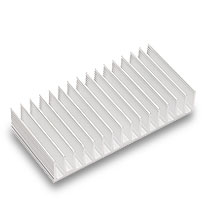
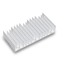
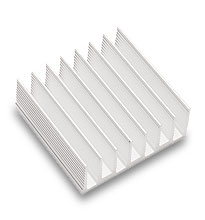
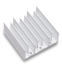
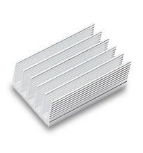
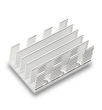
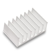
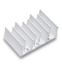
| Heat Sinks used with Vicor’s Maxi-Size Modules (not for VI-200 modules) | |||||||||||
| Description | P/N | RoHS | Technical Drawing | ||||||||
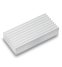 |
0.40″ longitudinal fins, threaded mounting* | 30482 | PDF |DXF | ||||||||
| 0.90″ longitudinal fins, threaded mounting* | 30188 | PDF |DXF | |||||||||
|
|
|||||||||||
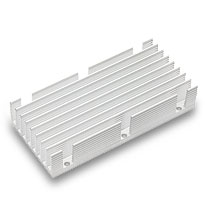 |
0.40″ longitudinal fins, thru-hole mounting | 30718 | PDF |DXF | ||||||||
| 0.90″ longitudinal fins, thru-hole mounting | 30181 | PDF |DXF | |||||||||
|
|
|||||||||||
 |
0.40″ transverse fins, threaded mounting* | 30778 | PDF |DXF | ||||||||
| 0.90″ transverse fins, threaded mounting* | 30196 | PDF |DXF | |||||||||
 |
0.40″ transverse fins, thru-hole mounting | 30720 | PDF |DXF | ||||||||
| 0.90″ transverse fins, thru-hole mounting | 30723 | PDF |DXF | |||||||||
| * NOT for use with threaded baseplates | |||||||||||
| Heat Sink Thermal Data and Calculator | |||||||||||
| Heat Sinks used with Vicor’s Mini-Size Modules (not for VI-J00 modules) | |||||||||||
| Description | P/N | RoHS | Technical Drawing | ||||||||
 |
0.40″ longitudinal fins, threaded mounting* | 32188 | PDF |DXF | ||||||||
| 0.90″ longitudinal fins, threaded mounting* | 30189 | PDF |DXF | |||||||||
|
|
|||||||||||
 |
0.40″ longitudinal fins, thru-hole mounting | 30195 | PDF |DXF | ||||||||
| 0.90″ longitudinal fins, thru-hole mounting | 30182 | PDF |DXF | |||||||||
|
|
|||||||||||
 |
0.40″ transverse fins, threaded mounting* | 30184 | PDF |DXF | ||||||||
| 0.90″ transverse fins, threaded mounting | 30269 | PDF |DXF | |||||||||
 |
0.40″ transverse fins, thru-hole mounting | 30721 | PDF |DXF | ||||||||
| 0.90″ transverse fins, thru-hole mounting | 30724 | PDF |DXF | |||||||||
| * NOT for use with threaded baseplates | |||||||||||
| Heat Sink Thermal Data and Calculator | |||||||||||
| Heat Sinks used with Vicor’s Micro-Size Modules | |||||||||||
| Description | P/N | RoHS | Technical Drawing | ||||||||
 |
0.40″ longitudinal fins, threaded mounting* | 32174 | PDF |DXF | ||||||||
| 0.90″ longitudinal fins, threaded mounting* | 30190 | PDF |DXF | |||||||||
|
|
|||||||||||
 |
0.40″ longitudinal fins, thru-hole mounting | 30719 | PDF |DXF | ||||||||
| 0.90″ longitudinal fins, thru-hole mounting | 30183 | PDF |DXF | |||||||||
|
|
|||||||||||
 |
0.40″ transverse fins, threaded mounting* | 32173 | PDF |DXF | ||||||||
| 0.90″ transverse fins, threaded mounting* | 30270 | PDF |DXF | |||||||||
 |
0.40″ transverse fins, thru-hole mounting | 30722 | PDF |DXF | ||||||||
| 0.90″ transverse fins, thru-hole mounting | 30725 | PDF |DXF | |||||||||
| * NOT for use with threaded baseplates | |||||||||||
| Heat Sink Thermal Data and Calculator | |||||||||||
| Low-Profile Side-Fin Heat Sinks (Height only 0.125″ above module baseplate) | |||||||||||
| Description | P/N | RoHS | Technical Drawing | ||||||||
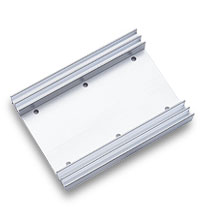 |
0.55″ Side-Fin Heat Sink for Maxi-Sized Modules | 30096 | |||||||||
|
|
|||||||||||
 |
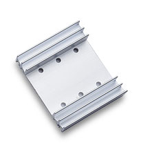
0.55″ Side-Fin Heat Sink for Mini-Sized Modules | 32190 | |||||||||
|
|
|||||||||||
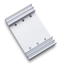
| 0.55″ Side-Fin Heat Sink for Micro-Sized Modules | 30095 | ||||||||||
 |
|||||||||||
| Heat Sink Thermal Data and Calculator | |||||||||||
| ThermMate Thermal Pads (10 pieces per package) | |||||||||||
| Description | P/N | Thickness | RoHS | Technical Drawing | |||||||
 |
For use with Vicor Maxi-size modules* | 20263 | 0.007″ | PDF |DXF | |||||||
| For use with Vicor Mini-size modules* | 20264 | 0.007″ | PDF |DXF | ||||||||
| For use with Vicor Micro-size modules | 20265 | 0.007″ | PDF |DXF | ||||||||
| * NOT for use with VI-200 or VI-J00 modules | |||||||||||